Internal micro-channel heat sink

A channel and internal micro technology, applied in the direction of laser components, electrical components, lasers, etc., can solve the problem of poor oxygen-free copper

Active Publication Date: 2014-09-17
CHENGDU 3D CHANGE TECH
View PDF7 Cites 15 Cited by
  • Summary
  • Abstract
  • Description
  • Claims
  • Application Information

AI Technical Summary

Problems solved by technology

However, the traditional oxygen-free copper does not

Method used


Image

  • Internal micro-channel heat sink
  • Internal micro-channel heat sink
  • Internal micro-channel heat sink

Examples


Embodiment 1

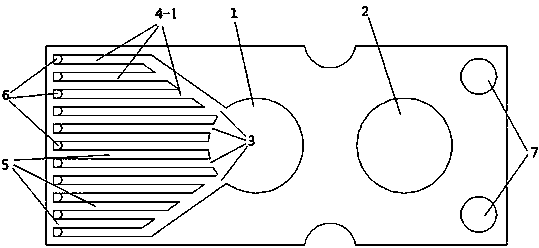
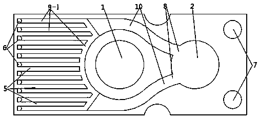
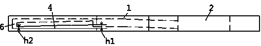
[0042] The manufacturing method of the structure in this example is a narrow channel heat sink integrally formed by additive manufacturing technology. The cooling water enters the water inlet channel 4 between the channel walls 5 sequentially from the water inlet hole 1 through the water inlet channel hole 3, the water inlet channel, and then The bonding front end of the heat sink chip enters the water outlet channel 9 through the reverse water hole 6, and after passing through the confluence channel 10, it enters the water outlet hole 2 through the water outlet channel hole 8, thereby completing a cycle of refrigeration. The reasons for increasing the number of inlet and outlet passages 4 and making the passage walls as long as possible are to increase the heat exchange area as much as possible, reduce the velocity of liquid movement, and improve heat exchange efficiency. The channel height h3 at the reverse water hole 6 of the water outlet channel 9 is greater than the channe...

Embodiment 2

[0044] The manufacturing method of the structure in this example is a narrow channel heat sink integrally formed by additive manufacturing technology. The cooling water enters the water inlet channel 4 between the channel walls 5 sequentially from the water inlet hole 1 through the water inlet channel hole 3, the water inlet channel, and then The bonding front end of the heat sink chip enters the water outlet channel 9 through the reverse water hole 6, and after passing through the confluence channel 10, it enters the water outlet hole 2 through the water outlet channel hole 8, thereby completing a cycle of refrigeration. The reasons for increasing the water inlet and outlet channels and making the channel walls as long as possible are to increase the heat transfer area as much as possible, reduce the liquid movement speed, and improve the heat transfer efficiency. The channel height h3 at the reverse water hole 6 of the water outlet channel 9 is greater than the channel width ...

Embodiment 3

[0049] The manufacturing method of the structure in this example is a narrow channel heat sink integrally formed by additive manufacturing technology. The cooling water enters the water inlet channel 4 between the channel walls 5 sequentially from the water inlet hole 1 through the water inlet channel hole 3, the water inlet channel, and then The bonding front end of the heat sink chip enters the water outlet channel 9 through the reverse water hole 6, and then enters the water outlet hole 2 through the water outlet channel hole 8 after passing through the confluence channel 10, thereby completing a cycle of refrigeration. The reasons for increasing the water inlet and outlet channels and making the channel walls as long as possible are to increase the heat transfer area as much as possible, reduce the liquid movement speed, and improve the heat transfer efficiency. The channel height h3 at the reverse water hole 6 of the water outlet channel 9 is greater than the channel width...


PUM


Abstract

The invention provides an internal micro-channel heat sink and relates to the field of heat dissipation structures of a semiconductor laser, an array device and a large-scale integrated circuit. The internal micro-channel heat sink mainly overcomes the defects that an existing heat sink is low in heat exchange efficiency and reduces heat resistance and pressure drop. The internal micro-channel heat sink comprises a water outlet layer, a water distribution layer and a water inlet layer which are arranged in sequence from top to bottom. A water inlet hole is formed in the water inlet layer and connected with water inlet channels. Return water holes are formed in the water distribution layer. A water outlet hole is formed in the water outlet layer and connected with water outlet channels. The water inlet channels are connected with the water outlet channels through the return water holes. The internal micro-channel heat sink is characterized in that the apertures of the water inlet channels decrease in the direction from the water inlet hole to the return water holes; the apertures of the water outlet channels decrease in the direction from the return water holes to the water outlet hole.

Description

technical field [0001] The invention relates to an internal microchannel cooling heat sink designed for semiconductor lasers, array devices, large-scale integrated circuits and other heat dissipation cooling devices, and belongs to the technical field of semiconductor optoelectronics. Background technique [0002] The inner microchannel cooled heat sink is a kind of modular microchannel cooler (Modular Microchannel Cooled Heatsinks, referred to as MCC). The advent of this effective low thermal resistance heat sink is closely related to the development of arrays, especially fully filled laser diode arrays for high duty cycle and even CW operation. MCC is produced by anisotropic chemical etching in silicon, and can be used as building blocks to overlap large two-dimensional structures according to the design needs of diode arrays. The low thermal resistance of MCC is dependent on the liquid refrigerant and its laminar flow through MCC. Its good thermal control performance is ...

Claims


Application Information

Patent Timeline
IPC IPC(8): H01S5/024
Inventor 王智勇李从洋闫岸茹张冬云
Owner CHENGDU 3D CHANGE TECH
Why Eureka
Try Eureka