A urea scale removing device used for a bottom tail tube of a flue gas denitration urea pyrolyzing furnace

A pyrolysis furnace and urea technology, applied in the field of flue gas denitrification equipment, can solve problems such as large heat consumption, urea blockage, atomizing nozzle failure, etc., and achieve the effects of easy maintenance and maintenance, high energy utilization, and reduced labor costs.

Active Publication Date: 2014-10-29
北京中新国能环保科技有限公司
View PDF3 Cites 1 Cited by
  • Summary
  • Abstract
  • Description
  • Claims
  • Application Information

AI Technical Summary

Problems solved by technology

Since the tailpipe at the bottom of the pyrolysis furnace is connected to the pipeline by flanges, and the tailpipe and the pipeline form a conical surface, the top is large and the bottom is small, the following problems often occur in the actual production process: 1) The bottom is caused by insufficient pyrolysis of urea. Excessive accumulation of urea in the tailpipe will reduce the outlet air volume and insufficient ammonia supply to the system, which will affect the efficiency and reliability of the denitrification system; If it is sprayed directly into the urea pyrolysis furnace without atomization, the pyrolysis effect will be affected, and urea will be deposited directly on the tailpipe at the bottom of the pyrolysis furnace to cause blockage; 3) The thermal insulation design or construction of the pyrolysis furnace and its outlet pipeline is not in place, resulting in The temperature of the mixed gas pipeline is lower than the reverse reaction temperature of urea decomposition products, and urea crystallization occurs in the pipeline, which leads to pipeline blockage
Due to its specific equipment structure, it is very inconvenient to install, overhaul, and maintain the urea pyrolysis device at this place, and measures such as heating with heating tape at the bottom of the equipment are adopted. Since the pyrolysis furnace adopts a metal structure, the heat conduction is fast, and during the heating process It is difficult to reach the decomposition temperature of urea, resulting in high heat consumption and poor effect

Method used


Image

  • A urea scale removing device used for a bottom tail tube of a flue gas denitration urea pyrolyzing furnace
  • A urea scale removing device used for a bottom tail tube of a flue gas denitration urea pyrolyzing furnace
  • A urea scale removing device used for a bottom tail tube of a flue gas denitration urea pyrolyzing furnace

Examples


Embodiment Construction

[0023] The following examples are further detailed descriptions of the present invention.

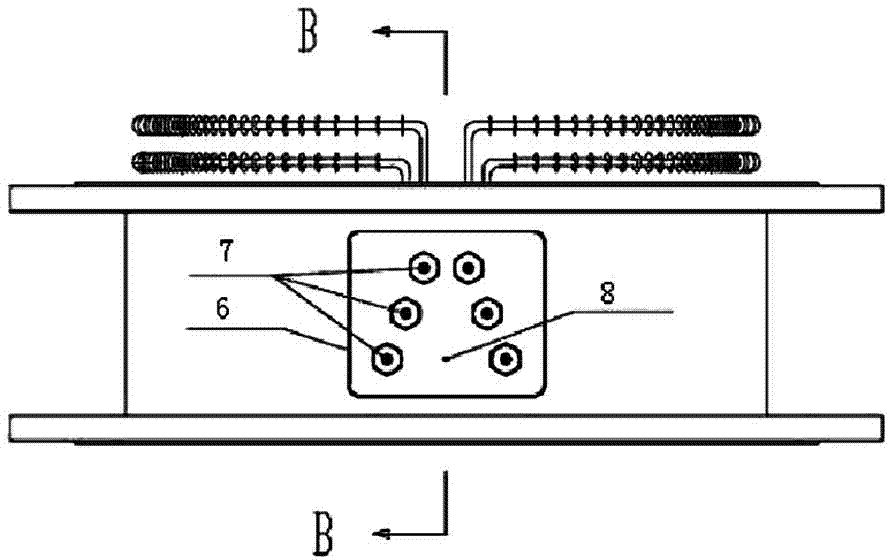
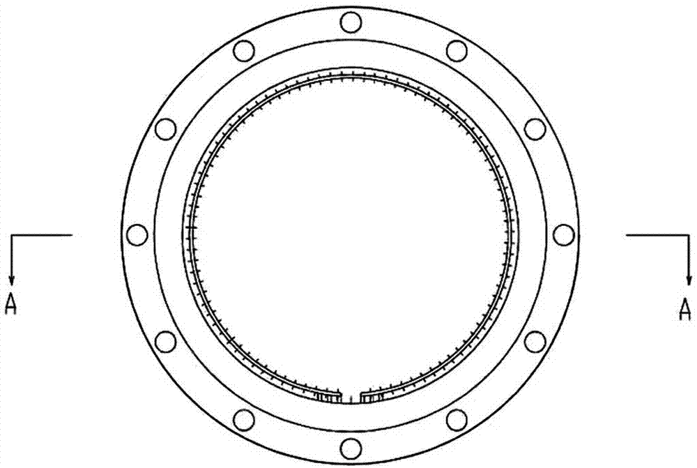
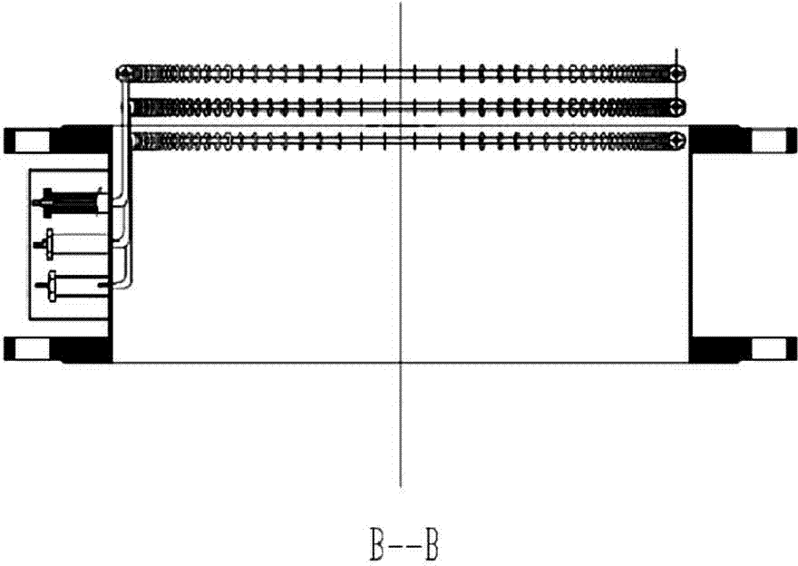
[0024] Examples see Figure 1-6 As shown, the urea decomposition device for the bottom tailpipe of the urea pyrolysis furnace used for flue gas denitrification consists of an electric heating body part and an electric control part. In the actual operation process, the urea solution is atomized in the pyrolysis furnace and decomposed at 350°C to 600°C, mixed with ammonia gas, hot air and possibly undecomposed urea through the tailpipe at the bottom of the pyrolysis furnace, urea The pyrolysis device enters the hot air duct and enters the catalyst layer through the ammonia injection grid for selective catalytic reduction and denitrification reaction. The urea decomposition device can control the opening and closing of the relay of the decomposition device according to the temperature measurement signal of the thermal resistance at the bottom of the pyrolysis furnace to control the temper...


PUM

PropertyMeasurementUnit
diameteraaaaaaaaaa

Abstract

A urea scale removing device used for a bottom tail tube of a flue gas denitration urea pyrolyzing furnace is disclosed. The urea scale removing device comprises an electrothermal decomposer and an automatic control device. The electrothermal decomposer comprises a lower flange (1), an upper flange (2) and a cylinder (3). The lower flange (1) and the upper flange (2) are respectively disposed at the two ends of the cylinder (3). The middle part of the cylinder (3) is provided with pipe heaters (4). The automatic control device is a junction box (6) disposed at the cylinder (3). The panel of the junction box (6) is provided with pipe heater binding posts (7) and an equipment grounding protection binding post (8). One end of each of the pipe heaters (4) is connected to one of the pipe heater binding posts (7). The urea pyrolyzing furnace adopts a separated type design, thus facilitating installation, maintenance and overhaul of the pipe heaters. Compared with traditional ribbon heater insulation manners, the manner of directly installing high-power pipe heaters at positions prone to deposition and crystallization is higher in the energy utilization rate and better in urea pyrolyzing effects.

Description

technical field [0001] The invention relates to the technical field of flue gas denitrification equipment, in particular to a urea fouling elimination device for the bottom tailpipe of a flue gas denitrification urea pyrolysis furnace. Background technique [0002] Selective catalytic reduction (selective catalytic reduction) denitrification process is currently the main denitrification process in coal-fired power plants. 2 and water. At present, the reducing agent used in industry is mainly ammonia or urea. The use of ammonia as the reducing agent requires the use of an ammonia evaporation supply system, that is, the liquid ammonia is first evaporated into ammonia gas, and then passes through the ammonia buffer tank, and then combined with air (using Dilution fan delivery) mixed in the mixer, then enter the ammonia injection grid, and finally enter the catalytic reactor for reaction. Due to the problems of fire prevention and explosion protection in transportation and sto...

Claims


Application Information

Patent Timeline
Patent Type & Authority Applications(China)
IPC IPC(8): C01C1/08
Inventor 张平凡杨超峰冯娟宋呈芳郭彤王飞范邵北史晓霞
Owner 北京中新国能环保科技有限公司
Why Eureka
Try Eureka