Waste gas treatment process and device in isophthaloyl dichloride/paraphthaloyl chloride production

A technology for treating terephthaloyl chloride and waste gas, which is applied in the fields of inorganic chemistry, sulfur compounds, and dispersed particles. It can solve the problems of difficult treatment of sulfite solution, low recovery rate of sulfur dioxide gas, and neglect of waste gas treatment, etc., and achieve reduction Output, easy operation, and improved utilization

Active Publication Date: 2014-11-12
SHANDONG KAISHENG NEW MATERIALS
View PDF7 Cites 7 Cited by
  • Summary
  • Abstract
  • Description
  • Claims
  • Application Information

AI Technical Summary

Problems solved by technology

[0002] At present, most of the sulfur dioxide and hydrogen chloride mixed waste gas produced in the reaction process of preparing iso/terephthaloyl chloride is treated, and the hydrogen chloride is converted into hydrochloric acid, and the sulfur dioxide is absorbed by an alkaline medium, resulting in a large amount of sulfite solution that is difficult to handle and poses a threat to the environment. Protection has brought a lot of pressure; even if some production units recycle sulfur dioxide, they a

Method used


Image

  • Waste gas treatment process and device in isophthaloyl dichloride/paraphthaloyl chloride production

Examples


Embodiment 1

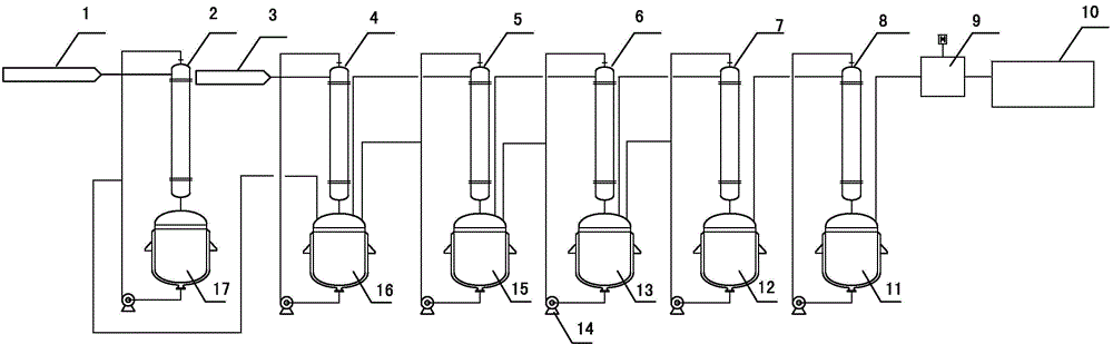
[0030] Sulfur dioxide and hydrogen chloride waste gas 3 produced in the reaction process using thionyl chloride to prepare m / terephthaloyl chloride enter the top of the primary absorption tower 4, and the unabsorbed waste gas enters the secondary absorption tower 5 through the top of the primary absorption tank 16 At the top, the remaining waste gas enters the top of the third-stage absorption tower 6 through the top of the second-stage absorption tank 15, and then enters the top of the fourth-stage absorption tower 7 through the top of the third-stage absorption tank 13, and the remaining sulfur dioxide gas passes through the fourth-stage absorption tank 12 after the fourth-stage absorption. The top enters the top of the drying tower 8, and the dried sulfur dioxide gas enters the sulfur dioxide pressurization device 9 from the top of the dry absorption tank 11, and the pressurized sulfur dioxide gas is transported to the thionyl chloride preparation device 10 for utilization, a...

Embodiment 2

[0032] The device structure of this embodiment is the same as that of Embodiment 1, the difference is that the gas phase entering the absorption tower, drying tower, and alkali absorption tower is absorbed by taking in air from the bottom of the tower and outlet from the top of the tower.

Embodiment 3

[0034] The device structure of this embodiment is the same as that of Embodiment 1. The gas phase entering the drying tower is absorbed by the way of air intake at the top of the tower and gas outlet at the bottom of the tower. The difference is that both the gas phase entering the absorption tower and the alkali absorption tower adopt the air intake at the bottom of the tower. , Absorption is carried out by way of gas outlet from the top of the tower.


PUM


Abstract

The invention relates to a waste gas treatment process and device in isophthaloyl dichloride/paraphthaloyl chloride production, and belongs to the technical field of waste gas treatment. The process includes the steps that sulfur dioxide waste gas and hydrogen chloride waste gas which are generated in the reaction process of preparing isophthaloyl dichloride/paraphthaloyl chloride through thionyl chloride are absorbed through an absorption tower and are then recycled through a drying tower and a pressurization device; waste gas generated at the feed stage and the thionyl chloride recycling and rectifying stage enters an alkali absorption tower, and then the solution obtained after absorption is conducted is sent to an absorption device to release sulfur dioxide gas for recycle. By means of the process, emission of waste gas is reduced, recycling of sulfur dioxide is achieved, and the utilization rate of sulfur dioxide is further increased; the invention further provides the waste gas treatment device which is easy and convenient to operate in isophthaloyl dichloride/paraphthaloyl chloride production.

Description

technical field [0001] The invention relates to a waste gas treatment process and device in the production of iso / terephthaloyl dichloride, belonging to the technical field of waste gas treatment. Background technique [0002] At present, most of the sulfur dioxide and hydrogen chloride mixed waste gas produced in the reaction process of preparing iso / terephthaloyl chloride is treated, and the hydrogen chloride is converted into hydrochloric acid, and the sulfur dioxide is absorbed by an alkaline medium, resulting in a large amount of sulfite solution that is difficult to handle and poses a threat to the environment. Protection has brought a lot of pressure; even if some production units recycle sulfur dioxide, they are only limited to the recovery of waste gas with high sulfur dioxide content produced in the reaction process of preparing iso / terephthaloyl chloride, while ignoring the content of sulfur dioxide Less waste gas treatment, the recovery rate of sulfur dioxide is ...

Claims


Application Information

Patent Timeline
IPC IPC(8): B01D53/14B01D53/18B01D53/26B01D53/78B01D53/50C01B17/56
Inventor 张善民谢圣斌毕义霞闫蓓蓓王荣海张泰铭王志亮张清新
Owner SHANDONG KAISHENG NEW MATERIALS
Why Eureka
Try Eureka