Jet device for supercritical fluid jet dyeing of yarns

A supercritical fluid and ejector technology, which can be used in spray/jet textile material processing, liquid/gas/vapor jet propulsion fabrics, liquid/gas/vapor processing indefinite-length textile materials, etc., can solve the problem of increasing the complexity of the device structure and Investment cost, inability to achieve large-scale continuous dyeing of dyed objects, high sealing requirements, etc., to achieve the effects of good levelness and continuity, tight structure, safe and convenient operation

Active Publication Date: 2014-12-03
SHANDONG UNIV
View PDF4 Cites 3 Cited by
  • Summary
  • Abstract
  • Description
  • Claims
  • Application Information

AI Technical Summary

Problems solved by technology

Although these devices can improve the production efficiency and the dyeing effect of the dyed object through various measures from the structure, but because the supercritical fluid dyeing operation is a high-pressure operation, high-pressure equipment must be used, and these devices have high requirements for the

Method used


Image

  • Jet device for supercritical fluid jet dyeing of yarns
  • Jet device for supercritical fluid jet dyeing of yarns
  • Jet device for supercritical fluid jet dyeing of yarns

Examples


Embodiment 1

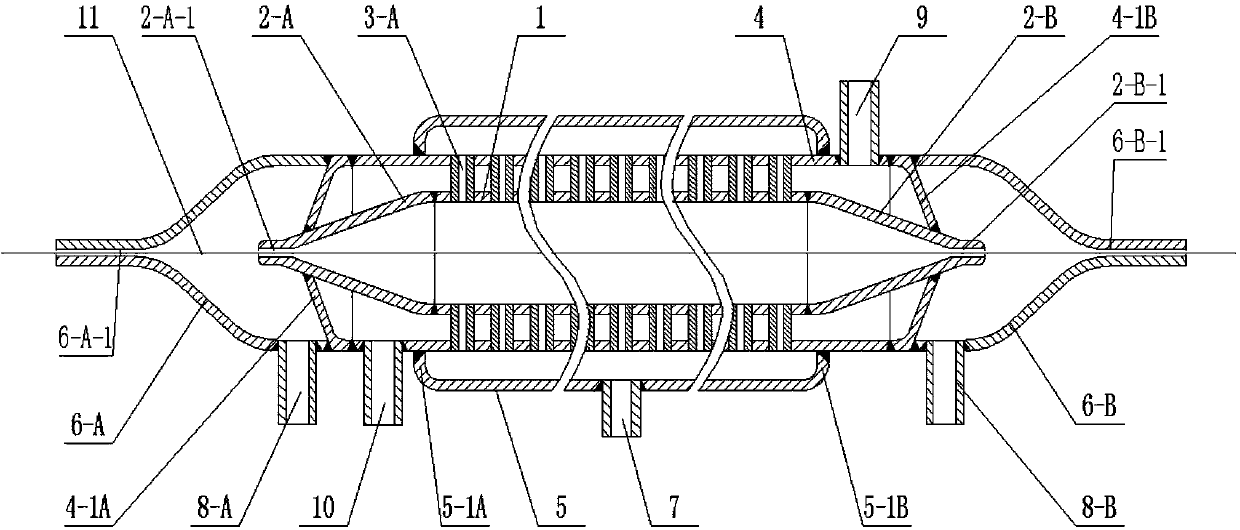
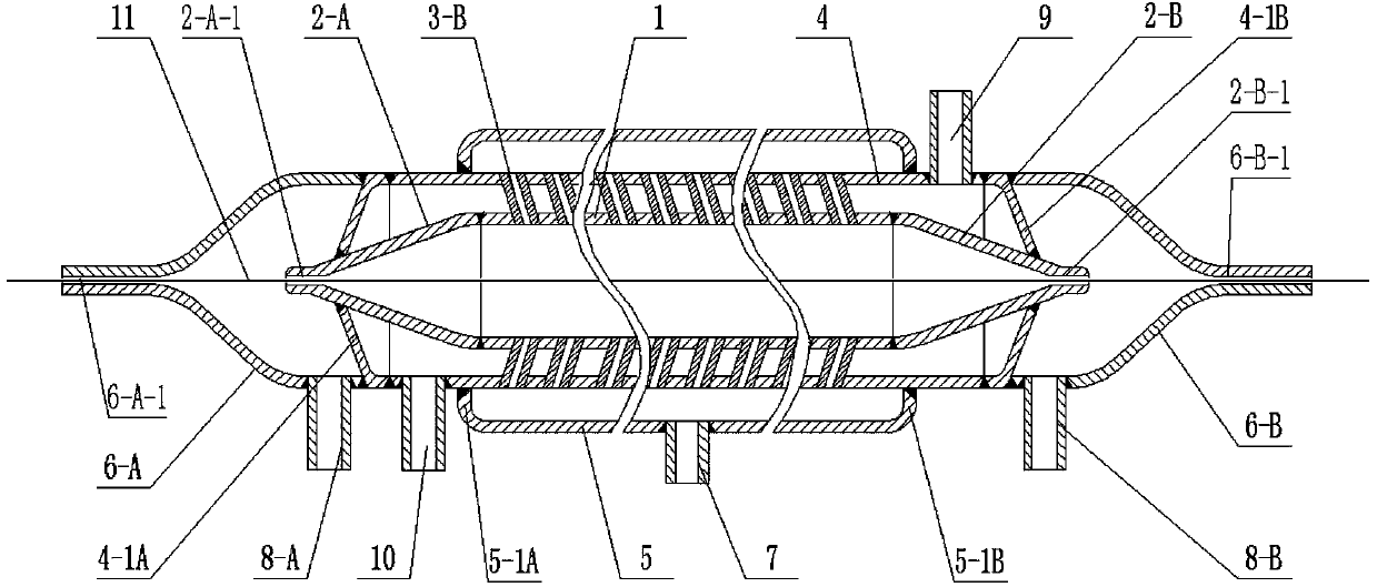
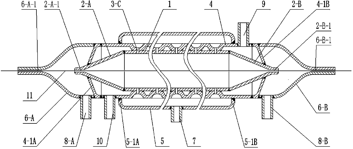
[0020] Embodiment one, the supercritical fluid jet dyeing yarn injector with heating tube is made of stainless steel material, such as figure 1 , figure 2 , image 3 and Figure 4 shown.

[0021] Depend on The spray hole distribution pipe 1, the big end and little endian The high pressure guide nozzle 2-A and 2-B, The heating pipe 4 and the heating pipe plug 4-1A and 4-1B, The fluid distribution pipe 5 and the fluid distribution pipe plugs 5-1A and 5-1B, the big end and little endian Low-pressure guide nozzles 6-A and 6-B, Directly installed orifice pipe 3-A or obliquely installed orifice pipe 3-B, Fluid inlet connection 7, Fluid outlet connections 8-A and 8-B, Steam inlet connection 9 and The steam outlet connecting pipe 10 is composed of; the number of spray holes is determined to be 12 according to the specific dyeing process conditions; the two ends of the spray hole distribution pipe 1 are coaxially welded and connected to the high-pressure guide...

Embodiment 2

[0032] Embodiment two, the supercritical fluid jet dyeing yarn injector without heating tube is made of stainless steel, such as Figure 4 and Figure 5 shown.

[0033] Depend on The spray hole distribution pipe 1, the big end and little endian The high pressure guide nozzle 2-A and 2-B, The fluid distribution pipe 5 and the fluid distribution pipe plugs 5-1A and 5-1B, the big end and little endian Low-pressure guide nozzles 6-A and 6-B, The fluid inlet connection 7, The fluid outlet connecting pipes 8-A and 8-B are formed; the number of spray holes is determined to be 15 according to the specific dyeing process conditions, and the two ends of the spray hole distribution pipe 1 are coaxially welded and connected to the high-pressure guide nozzles 2-A and 2- B, Drilling on nozzle distribution pipe 1 The small holes are divided into 5 circles, and 3 are evenly distributed in each circle. The distance between each circle and the outermost circle and the high-pre...


PUM


Abstract

The invention relates to the field of textile dyeing equipment, in particular to a jet device for supercritical fluid jet dyeing of yarns. According to the jet dyeing process, after installed in a supercritical fluid jet dying device, the jet device is connected with a supercritical fluid generation subsystem, a dye dissolution subsystem and a used fluid recovery and separation subsystem. According to the technical scheme, the jet device with or with no heating pipes comprises orifices, an orifice distribution pipe, high-pressure guide nozzles, a fluid distribution pipe, a fluid distribution pipe plug, low-pressure guide nozzles, a fluid inlet connecting pipe, a fluid outlet connecting pipe, a steam inlet connecting pipe and a steam outlet connecting pipe. By the use of the jet device, the problem that a high-pressure dyeing container is a necessity to the existing supercritical fluid jet dyeing device is solved; the jet device is simple in structure, safe and convenient to operate, good in dyeing uniformity and continuity, harmless to yarns under dyeing, and low in investment cost.

Description

1. Technical field [0001] The invention relates to the field of textile dyeing equipment, in particular to an injector for yarn dyeing by supercritical fluid spraying. 2. Technical Background [0002] The processing technology of traditional dyeing equipment has problems such as high water consumption, high energy consumption, long process, difficult sewage treatment and high cost. Supercritical fluid dyeing, especially supercritical carbon dioxide dyeing, uses supercritical fluid instead of water as the carrier of the dye to achieve water-free dyeing, thus fundamentally solving the problem of water pollution in the dyeing industry. At the same time, supercritical fluid dyeing technology has the advantages of supercritical fluid recycling, no pollution discharge, no drying of dyed objects, less fiber damage, simple and quick operation, high dyeing efficiency and low energy consumption, and has a good development and application prospect. [0003] At present, most of the sup...

Claims


Application Information

Patent Timeline
IPC IPC(8): D06B1/02D06B23/20D06B23/22
CPCD06B3/28D06B5/06
Inventor 王威强王明禄曲延鹏刘燕
Owner SHANDONG UNIV
Why Eureka
Try Eureka