
Machining method of metallurgical furnace launder

A processing method and metallurgical furnace technology, applied in the processing field of metallurgical furnace launders, can solve the problems of low strength of red copper or alloy copper, thick thickness of buried pipe casting body, affecting the normal production of metallurgical furnace, etc., and achieve excellent cooling effect and saving. Purchase cost, effect of grain refinement

Inactive Publication Date: 2014-12-10
SHANTOU HUAXING METALLURGICAL EQUIP CO LTD
View PDF7 Cites 3 Cited by
  • Summary
  • Abstract
  • Description
  • Claims
  • Application Information

AI Technical Summary

Problems solved by technology

[0005] 2) The body strength of cast copper or alloy copper is low, and the surface quality after molding is relatively rough, which increases the resistance of material flow in the molten state and increases unnecessary loss
If the casting surface is finished, it is easy to expose internal casting defects such as pores and cracks, and greatly increase the manufacturing cost
[0006] 3) The main body is buried in pipe casting, and there is a large air gap thermal resistance between the pre-embedded copper pipe and the main body. This is because it is difficult to achieve metallurgical bonding between the main body and the water pipe. In a high temperature working environment, the air gap thermal resistance is greatly weakened. Heat transfer capacity
[0007] 4) Due to the technical constraints of the outer diameter of the embedded copper pipe and the minimum bending radius, the thickness of the buried pipe casting body is relatively thick, resulting in a large design weight of the entire launder
[0008] The applicant found that the problem of the above-mentioned traditional launder is not only the material and manufacturing method used, but also its structure is very unreasonable, which leads to its poor heat transfer capacity, easy damage, and short life, and the launder needs to be repaired or replaced frequently. Thus affecting the normal production of the metallurgical furnace

Method used


Image

  • Machining method of metallurgical furnace launder
  • Machining method of metallurgical furnace launder
  • Machining method of metallurgical furnace launder

Examples


Embodiment 1

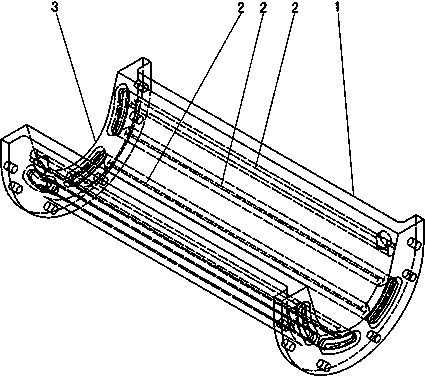
[0032] The processing method of the metallurgical furnace launder of the present embodiment is processed by combining forging slab and machining, including the following steps:

[0033] a. Forging the cast slab into semi-finished metallurgical furnace launder with curved surface;

[0034] b. Finishing the semi-finished products of metallurgical furnace launder components into finished metallurgical furnace launders.

[0035] The material of the cast slab is red copper or alloy copper.

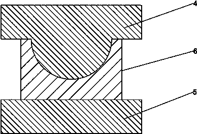
[0036] Such as figure 2 As shown, the forging is to forge and press the cast slab by a hydraulic press, and the thickness of the cast slab is twice the thickness of the finished product after forging; ≥98%IACS, corresponding thermal conductivity: λ≥381W / (m·K).

[0037] The finishing steps include:

[0038] b1. Use a special deep hole drilling machine tool to drill holes on the semi-finished product of the forged metallurgical furnace launder (processed into a cooling channel pass). The li...

Embodiment 2

[0043] The difference between the metallurgical furnace launder finished product and embodiment 1 in the present embodiment is:

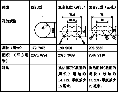
[0044] The cooling water channel 2 is a composite hole, and the composite hole is partially overlapped by two circular holes. The diameter of each circular hole is the same, and the heat exchange area (perimeter of the section) of the cooling water channel increases by about 14.71%.

Embodiment 3

[0046] The difference between the metallurgical furnace launder finished product and embodiment 1 in the present embodiment is:

[0047] The cooling water channel 2 is a composite hole, and the composite hole is partially overlapped by three circular holes. The diameters of the circular holes are different, and the heat exchange area (perimeter of the section) of the cooling water channel increases by about 17.23%.

[0048]Taking a finished metallurgical furnace launder with a length of 2m and an unfolded width of 1.5m as an example, in order to meet the performance requirements and life requirements of the traditional casting process, the thickness of the launder is usually designed to be more than 160mm. Thickness above 120mm (including 120mm) can meet the requirements. For the slab with the above compound pass type (three holes), under the condition of ensuring the same wall thickness of the cooling channel, one round hole (such as Φ55) is changed to three round holes supe...


PUM

PropertyMeasurementUnit
thermal conductivityaaaaaaaaaa

Abstract

Provided is a machining method of a metallurgical furnace launder. A mode that plate blank forging and machining are combined is used for machining. The method comprises the following steps that forged plate blanks are forged and pressed into a metallurgical furnace launder semi-finished product with an arc face; and a metallurgical furnace launder component semi-finished product is subjected to finish machining to form a metallurgical furnace launder finished product. The machined metallurgical furnace launder finished product comprises a launder body. The launder is formed in the top of the launder body. A plurality of cooling water channels are arranged in the launder body. The cooling water channels are communicated with each other in an end-to-tail mode. At least one water inlet and one water outlet are formed. A forming technology is changed into the mode that forging, pressing and machining are combined, so that body materials are compact, grain refining is achieved, mechanical property is good, heat conductivity is high, composite holes are used as the cooling water channels, the cooling performance of the cooling water channels is further improved, the improvements are combined so that the thickness of the launder body can be greatly reduced, a producer can know that the launder with good performance can be obtained with low cost increased, frequent maintaining or replacing is of no need, influence on normal production can be greatly reduced, and production efficiency is greatly improved.

Description

technical field [0001] The invention relates to a processing method for a launder of a metallurgical furnace. Background technique [0002] At present, the launders used in commonly used metallurgical furnaces are used to transport materials in a molten state (such as molten iron or slag). A complete launder is usually connected by one or several launders. It is often connected by means of flanges and bolts. The main body of the launder is usually made of red copper or alloy copper. The traditional process is to pre-embed the cooling copper tube, and then pour the copper tube and molten copper as a whole. After forming, the cross-sectional shape of the runner has a "U" shape, etc. [0003] The disadvantages of the above-mentioned traditional casting process are as follows: [0004] 1) The body is cast and formed, which is prone to sand holes, shrinkage defects, pores, pinhole defects and crack tendencies. This is because the casting body shrinks a lot, and the body shrink...

Claims


Application Information

Patent Timeline
Patent Type & Authority Applications(China)
IPC IPC(8): B23P15/00
CPCB23P15/00
Inventor 佘京鹏李立鸿沈大伟陈名炯周兵其吴捷
Owner SHANTOU HUAXING METALLURGICAL EQUIP CO LTD
Learn More