Waste incineration treatment system

A treatment system and waste incineration technology, applied in the field of waste incineration treatment systems, can solve the problems of immovability, limited use, and easy explosion, so as to improve treatment efficiency and quality, improve material combustion efficiency, and ensure complete combustion Effect

Active Publication Date: 2014-12-17
TANGSHAN CHENXI MACHINERY MFG
View PDF4 Cites 1 Cited by
  • Summary
  • Abstract
  • Description
  • Claims
  • Application Information

AI Technical Summary

Problems solved by technology

[0003] 1. Since the municipal waste is not classified, the volume and quality of the waste at each conveying end face are not the same with the traditional uniform-speed conveying method, varying from high to low, large and small, which affects the quality and efficiency of incineration;
[0004] 2. After the waste incineration in the traditional incineration rotary kiln is completed, the waste residue falls into the slag remover. Since most of the existing slag removers are in the open cooling mode, the gas generated during the transportation process is directly discharged into the atmosphere, causing environmental pollution ; and most of the existing slag removal machines are fixed installations, which cannot be moved, have limited use, and are not easy to overhaul;
[0005] 3. The traditional combustion chamber is the space for flue gas discharge, and it is difficult to make the flue gas discharge meet the emission standard
[0006] 4. The traditional combustion system does not have facilities for strict measurement and control of negative pressure, resulting in unstable temperature control in the combustion furnace, resulting in coking and inexhaustible emissions
[0007] 5. The traditional combustion system does not have a strict flue gas combustion control system in the second combustion chamber, making the safety of waste incineration flue gas emission a problem recognized by the world
[0008] 6. Incomplete explosion-proof safety facilities, prone to explosion

Method used


Image

  • Waste incineration treatment system
  • Waste incineration treatment system
  • Waste incineration treatment system

Examples


Embodiment Construction

[0035] The present invention will be further described below in conjunction with the accompanying drawings.

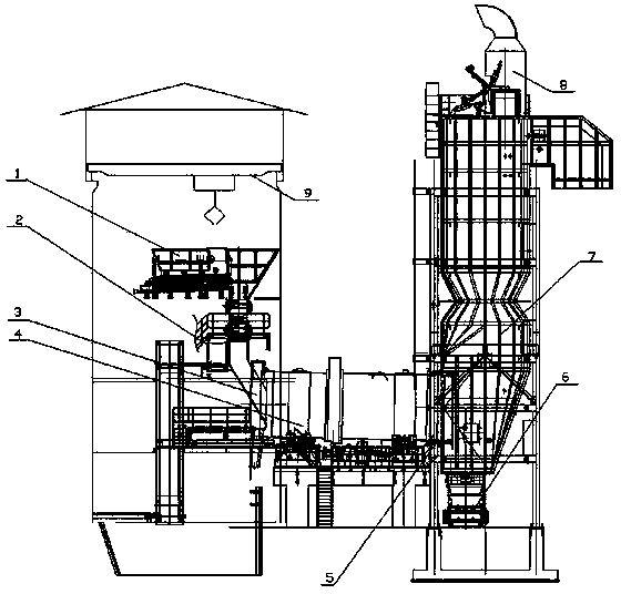
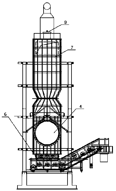
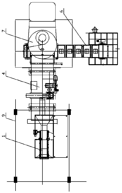
[0036] See attached Figure 1-8 , The waste incineration treatment system disclosed in the present invention includes a lifting frame 9, a bulk material feeding device 1, a small package material conveying device 2, an incineration rotary kiln 4, a slag remover 6 and a secondary combustion chamber 7. The unsorted bulk garbage is fed by the bulk material feeding device, and the classified dangerous goods are pressed into small packages, which are fed by the small package material conveying device. The sprocket conveying mechanism sends out, and the flue gas produced by incineration is fully burned again in the second combustion chamber and then discharged.

[0037] The bulk material feeding device comprises an upper hopper 10, an apron conveyor 17 and an unloading passage, the apron conveyor is arranged below the upper hopper 10, and one side of the upper hopper 10 is ...


PUM


Abstract

The invention discloses a waste incineration treatment system. The waste incineration treatment system comprises a lifting frame, a feeding device, an incineration rotary kiln, a slag remover and a secondary combustion chamber. A bulk feeding device comprises a feeding funnel, a plate conveyer and a discharging channel; a weighing platform and two gates are arranged in the discharging channel; a small-package material conveyer device comprises a bucket feeding conveyer, an elevator, a bucket discharging conveyer, a sealed box body, a secondary conveyer and a pusher; two side faces of the sealed box body are provided with two gates, and door panels are in sliding fit with the top of the sealed box body; the slag remover comprises a shell, a chain wheel conveying mechanism and an anti-explosion valve; the shell is of an enclosed structure, and the chain wheel conveying mechanism is arranged on a bottom plate of the shell; a plurality of groups of travelling rollers are arranged at the bottom; the middle of the secondary combustion chamber is of a venturi structure, and an air blowing port is formed at a small-caliber position. The waste incineration treatment system is simple in structure and low in construction cost and ensures quantitative, uniform and continuous feeding, the material combustion efficiency is improved, flue gas is combusted thoroughly, pollution is reduced, the treatment efficiency and the treatment quality are improved, and the emission of the flue gas on standard is guaranteed.

Description

technical field [0001] The invention relates to a garbage incineration treatment system, which belongs to the field of environmental protection machinery. Background technique [0002] The existing waste incineration treatment equipment mainly includes incineration rotary kilns, grate furnaces, fluidized bed furnaces, etc. Due to the variety of urban waste, many of them are not or cannot be classified in detail, resulting in insufficient and thorough combustion of the waste. Harmful gases such as dioxins, heavy metals, and sulfur dioxide are discharged up to standard. When using traditional incineration to dispose of garbage, there are the following deficiencies: [0003] 1. Since the municipal waste is not classified, the volume and quality of the waste at each conveying end face are not the same with the traditional uniform-speed conveying method, varying from high to low, large and small, which affects the quality and efficiency of incineration; [0004] 2. After the wa...

Claims


Application Information

Patent Timeline
Patent Type & Authority Applications(China)
IPC IPC(8): F23G5/16F23G5/44
Inventor 陈沛然牛伟光赵立杰曹敬龙陈顺金陈福顺
Owner TANGSHAN CHENXI MACHINERY MFG
Why Eureka
Try Eureka