Compensation device and drive device

A compensation device and operational amplification technology, applied in the field of signal processing, can solve problems such as reducing drive efficiency and increasing load loss

Inactive Publication Date: 2018-07-10
GUANGDONG VTRON TECH CO LTD
View PDF7 Cites 0 Cited by
  • Summary
  • Abstract
  • Description
  • Claims
  • Application Information

AI Technical Summary

Problems solved by technology

[0004] Based on this, it is necessary to provide a compensating device and a driving device for the above-mentioned driving circuit, which will reduce the driving efficiency and further increase the load loss.

Method used


Image

  • Compensation device and drive device
  • Compensation device and drive device
  • Compensation device and drive device

Examples


Embodiment Construction

[0013] In order to make the object, technical solution and advantages of the present invention clearer, the present invention will be further described in detail below in conjunction with the accompanying drawings and embodiments. It should be understood that the specific embodiments described here are only used to explain the present invention, not to limit the present invention.

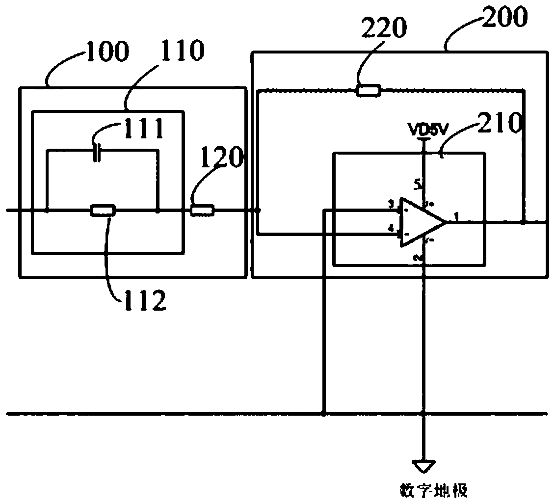
[0014] see figure 1 , figure 1 It is a structural schematic diagram of the first embodiment of the compensation device of the present invention.

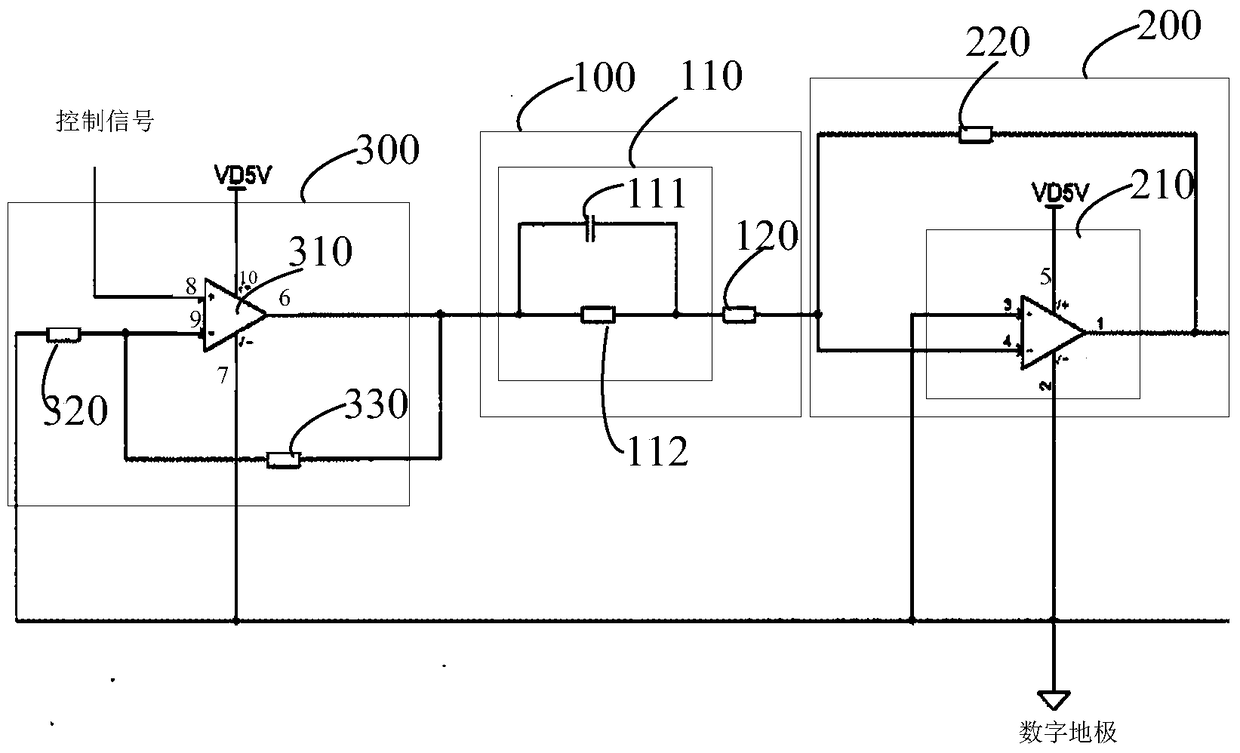
[0015] The compensation device described in this embodiment includes a voltage stabilizing unit 200 and a zero point adjustment unit 100 for canceling the first-order system pole of a metal oxide half field effect transistor. The zero point adjustment unit 100 includes a series phase shifting circuit 110 and a voltage dividing resistor 120, the phase shifting circuit 110 includes a parallel phase shifting capacitor 111 and a phase shifting resistor 112...


PUM


Abstract

The invention discloses a compensating device and a driving device. The compensating device includes a voltage stabilizing unit and a zero point adjusting unit for canceling the first-order system pole of a metal-oxide-semiconductor field effect transistor. The zero point adjusting unit includes a series phase shifting unit. circuit and a voltage dividing resistor, the phase-shifting circuit includes a parallel phase-shifting capacitor and a phase-shifting resistor, the voltage stabilizing unit includes an operational amplifier unit and a feedback resistor, and the feedback resistor is connected to the output terminal of the operational amplifier unit and Between the inverting input terminals, the non-inverting input terminal of the operational amplifier unit is grounded, and the voltage dividing resistor is connected between the phase shifting circuit and the inverting input terminal of the operational amplifier unit. Implement the device of the present invention, can offset the pole of the first-order system of MOSFET circuit, make the pole of compensation device become the pole of the first-order system of MOSFET circuit after compensation, adjust the constant of its circuit, shorten the output current rise time of MOSFET, accelerate output current rise rate.

Description

technical field [0001] The invention relates to the technical field of signal processing, in particular to a compensating device and a driving device. Background technique [0002] The drive circuit of the optical-mechanical light source device usually uses a power MOSFET (Metal-Oxide-Semiconductor Field-Effect Transistor) for energy conversion. In the switching of the MOSFET, it is controlled by PWM (Pulse Width Modulation) IC (integrated circuit, integrated circuit) output drive voltage to control the current size of the MOSFET output. [0003] The driving voltage waveform output by the control IC is usually a step square wave, and the current waveform output by the MOSFET is an approximate step waveform. This step current waveform is affected by parameters such as the MOSFET's own input capacitance and wiring inductance. This current waveform has a very slow rise time, which greatly prolongs the response time of the MOSFET, reduces the driving efficiency, and increases t...

Claims


Application Information

Patent Timeline
Patent Type & Authority Patents(China)
IPC IPC(8): H03K19/0944
Inventor 帅孟奇
Owner GUANGDONG VTRON TECH CO LTD
Why Eureka
Try Eureka