Electrolyte material, liquid composition, and membrane electrode assembly for polymer electrolyte fuel cell

An electrolyte material and polymer technology, applied in solid electrolyte fuel cells, fuel cells, battery electrodes, etc., can solve problems such as easy cracking, and achieve the effect of not easy cracking and good power generation characteristics

Active Publication Date: 2014-12-17
ASAHI GLASS CO LTD
View PDF15 Cites 13 Cited by
  • Summary
  • Abstract
  • Description
  • Claims
  • Application Information

AI Technical Summary

Problems solved by technology

[0005] However, the catalyst layer containing this electrolyte material is the same as the unit containing one ion-exchange group and all hydrogen atoms bonded to carbon atoms except H+ of the ion-exchange group are replaced with fluorine atoms. Compared with the catalyst layer of the electrolyte material based on the polymer of the tetrafluoroethylene (hereinafter referred to as TFE) unit, it is harder and brittle, so there is a problem that it is prone to cracking

Method used

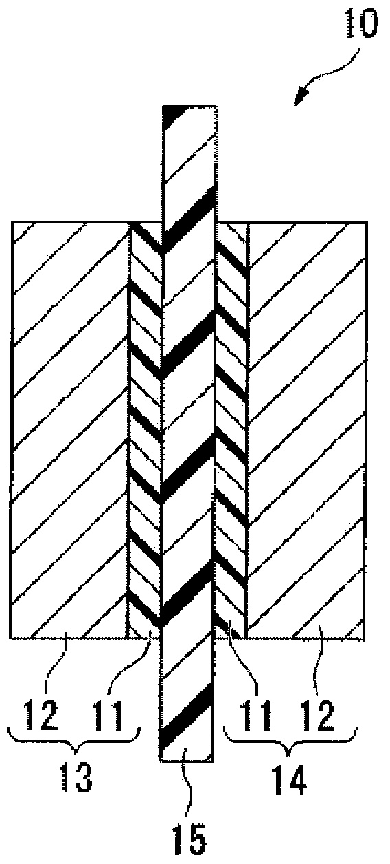
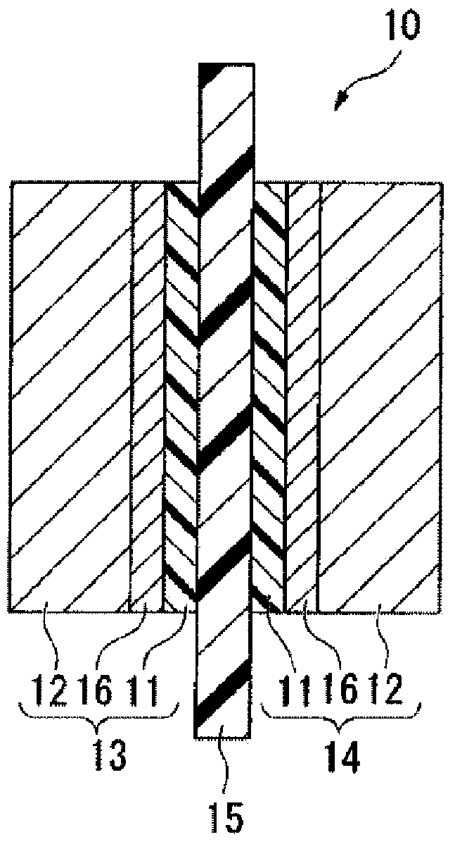

Image

  • Electrolyte material, liquid composition, and membrane electrode assembly for polymer electrolyte fuel cell
  • Electrolyte material, liquid composition, and membrane electrode assembly for polymer electrolyte fuel cell
  • Electrolyte material, liquid composition, and membrane electrode assembly for polymer electrolyte fuel cell

Examples


manufacture example

[0424] (manufacture of liquid composition)

[0425] A polymer (F') composed of compounds (m12-1), (m11-1) and TFE was obtained by the same method as in Example 5 described on page 29 of International Publication No. 2008 / 090990. Then, by the same method as Example 1 described later, polymer (F') -SO 2 F is converted into a sulfonic acid group to obtain a polymer (H'). The ion exchange capacity of the polymer (H') was 1.5 meq / g dry resin.

[0426] Add 370g polymer (H ') in the heat-resistant and corrosion-resistant nickel-based alloy autoclave of internal volume 2.5L, add the mixed solvent (water / ethanol=50 / 50 mass ratio) of water and ethanol again, solid content concentration Adjusted to 26% by mass. While stirring at a rotation speed of 150 rpm using a double ribbon impeller, the temperature was raised to 120° C. and stirred for 15 hours. Next, 200 g of water was added, the solvent composition was adjusted to water / ethanol=58 / 42 mass ratio, the solid content concentration...

example 1

[0434] (Manufacture of Polymer (F))

[0435] 150.0 g of compound (m12-1), 29.6 g of compound (m32-1), 32.2 g of compound (m21-1) and 63.5 mg of compound (i-1) were charged into a stainless steel autoclave with an inner volume of 230 mL, and the Fully degassed under nitrogen cooling. Then, 8.9 g of TFE was introduced into the system, and the temperature was raised to 10°C. The pressure at this time was 0.15 MPaG (gauge pressure). After stirring at 10° C. for 48 hours, the gas in the system was purged, and the autoclave was returned to room temperature to complete the reaction.

[0436] After diluting the product with compound (s-1), compound (s-2) was added thereto, and the polymer was aggregated and filtered. Then, the polymer was stirred in compound (s-1), re-agglomerated with compound (s-2), and dried under reduced pressure at 80° C. overnight to obtain polymer (F-1). The yield was 42.3g. Table 1 shows the ratio of each unit.

[0437] (Manufacture of Polymer (H))

[0...

example 15

[0450] 231.0 g of compound (m11-4), 13.0 g of compound (m31-2), 8.5 g of compound (m21-1) and 25.3 mg of compound (i-2) were charged into a stainless steel autoclave with an inner volume of 230 mL. Fully degassed under nitrogen cooling. Then, the temperature was raised to 100° C., TFE was introduced into the system, and the pressure was maintained at 0.3 MPaG to start polymerization. During polymerization, TFE was continuously added to keep the pressure constant at 0.3 MPaG. In addition, compound (m21-1) was continuously added at a rate of 1.0 g for 1 hour. After 10 hours, the gas in the system was purged, and the autoclave was returned to room temperature to complete the reaction. After the polymerization, the same procedure as in Example 1 was carried out to obtain a polymer (F-15), a polymer (H-15), a liquid compound (D-15), a catalyst layer (E-15), and a membrane electrode assembly. The results are shown in Table 3 and Table 5.


PUM


Abstract

Provided are a membrane electrode assembly that has excellent power generation properties and is less susceptible to breaking of a catalyst layer even under low-humidity to no-humidity conditions as well as under high-humidity conditions, and an electrolyte material suitable for the catalyst layer of the membrane electrode assembly. Used is an electrolyte material comprising a polymer (H) including: a unit (A) which has an ion exchange group and in which all hydrogen atoms bonded to carbon atoms are substituted by fluorine atoms; a unit (B) which has a five-membered ring and in which all hydrogen atoms bonded to carbon atoms are substituted by fluorine atoms; and a unit (C) which has neither an ion exchange group nor a ring structure, has an ether bond, and has an ether equivalent of 350 or less as established by formula (I), and in which all hydrogen atoms bonded to carbon atoms are substituted by fluorine atoms. Formula (I): Ether equivalent = the molecular weight of the monomer forming the unit (C) / the number of ether bonds in the monomer forming the unit (C).

Description

technical field [0001] The present invention relates to an electrolyte material for a polymer fuel cell, a liquid composition containing the electrolyte material, and a membrane electrode assembly for a polymer fuel cell containing the electrolyte material in a catalyst layer. Background technique [0002] In order to simplify and reduce the cost of the fuel cell system, polymer electrolyte fuel cells are required to operate under low-humidification or non-humidification conditions where the relative humidity of reaction gases (fuel gas and oxidant gas) is low. [0003] The following materials have been proposed as electrolyte materials for catalyst layers that can provide a membrane-electrode assembly for a solid polymer fuel cell with good power generation characteristics under low-humidification or no-humidification conditions. [0004] A unit (A) having two ion-exchange groups and all hydrogen atoms bonded to carbon atoms except H+ of the ion-exchange groups replaced wit...

Claims


Application Information

Patent Timeline
Patent Type & Authority Applications(China)
IPC IPC(8): C08F216/12C08F224/00C08F234/02C08K5/05C08L29/10C08L37/00C08L45/00H01B1/06H01M8/02H01M8/10
CPCC08F214/184C08J5/2237C08L33/16H01B1/122H01M4/8668H01M4/926H01M8/1004H01M8/1023H01M8/1039H01M2008/1095H01M2300/0082Y02E60/50B01J39/20B01J41/14
Inventor 本村了齐藤贡下平哲司渡壁淳
Owner ASAHI GLASS CO LTD
Why Eureka
Try Eureka