Zero-sequence current suppression method for open-winding permanent magnet synchronous motor system powered by double inverters

A permanent magnet synchronous motor, open winding technology, applied in motor generator control, electronic commutation motor control, AC motor control, etc. Effect

Active Publication Date: 2016-09-28
HARBIN INST OF TECH
View PDF4 Cites 0 Cited by
  • Summary
  • Abstract
  • Description
  • Claims
  • Application Information

AI Technical Summary

Problems solved by technology

[0003] The purpose of the present invention is to solve the problem of zero-sequence current in the open-winding permanent magnet synchronous motor system powered by double inverters, and provide a zero-sequence current suppression of the open-winding permanent magnet synchronous motor system powered by double inverters method

Method used


Image

  • Zero-sequence current suppression method for open-winding permanent magnet synchronous motor system powered by double inverters
  • Zero-sequence current suppression method for open-winding permanent magnet synchronous motor system powered by double inverters
  • Zero-sequence current suppression method for open-winding permanent magnet synchronous motor system powered by double inverters

Examples


specific Embodiment approach 1

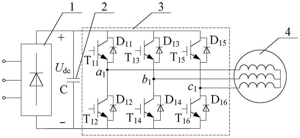
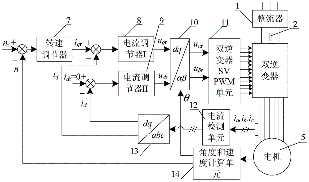
[0041] Specific implementation mode one: the following combination Figure 2 to Figure 8 Describe this embodiment, the zero-sequence current suppression method of the open-winding permanent magnet synchronous motor system powered by double inverters described in this embodiment, it is realized based on the open-type winding permanent magnet synchronous motor control system,

[0042] The motor control system includes a speed regulator 7, a current regulator I8, a current regulator II9, a dq-αβ coordinate transformation unit 10, a double inverter SVPWM unit 11, a current detection unit 12, an abc-dq coordinate transformation unit 13 and an angle with the speed calculation unit 14,

[0043] Its control method is: motor given speed n r After making a difference with the actual motor speed calculated by the angle and speed calculation unit 14, the given i of the q-axis current is generated by the speed regulator 7 qr , the given i of the q-axis current qr and the q-axis current ...

specific Embodiment approach 2

[0053] Specific implementation mode two: this implementation mode further explains implementation mode one, and the transformation formula of the abc-dq0 coordinate transformation unit 13-1 is:

[0054]

[0055] where i a is the current value of phase A at the motor input terminal, i b is the B-phase current value at the motor input terminal, i c is the C-phase current value of the motor input terminal.

specific Embodiment approach 3

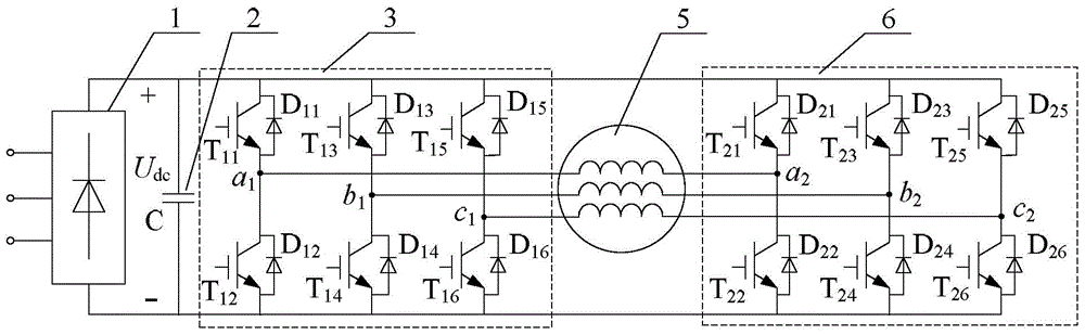
[0056] Specific implementation mode three: the following combination Figure 2 to Figure 11 This embodiment will be described. This embodiment will further describe the first embodiment. The dual-inverter SVPWM unit 11 according to the α-axis voltage reference value u αr , β-axis voltage reference value u βr and the desired motor zero-sequence voltage reference value u 0r Generate 12 switching signals of the double inverter, so that the actual zero-sequence voltage u of the output of the double inverter 0 Approaching to the desired motor zero-sequence voltage reference value u 0r The specific implementation method is:

[0057] The dual inverters are inverter I3 and inverter II6, and the voltage vector U output by the dual inverters passes through the voltage vector U output by inverter I3 1 Subtract the voltage vector U of the inverter II6 output 2 get:

[0058] U=U 1 –U 2 ;

[0059] According to the triangular rule of vector synthesis, the spatial distribution diagra...


PUM


Abstract

The invention discloses a zero-sequence current suppressing method for an open winding permanent magnet synchronous motor system powered by double inverters, belonging to the technical field of motor control. The invention aims to solve the problem of zero-sequence current in an open winding permanent magnet synchronous motor system powered by double inverters. It increases the zero-sequence current i on the basis of the vector control system 0 = 0 closed-loop control, to achieve the suppression of zero-sequence current, it calculates the zero-sequence current by detecting the three-phase current of the motor, and uses it as a feedback value to build a closed-loop control of zero-sequence current; the output of the zero-sequence current loop is zero-sequence voltage Given, the zero-sequence current is suppressed by regulating the zero-sequence voltage generated by the dual inverters. The invention is used for suppressing zero-sequence current in an open winding permanent magnet synchronous motor system powered by double inverters.

Description

technical field [0001] The invention relates to a zero-sequence current suppression method for an open winding permanent magnet synchronous motor system powered by double inverters, and belongs to the technical field of motor control. Background technique [0002] Due to its good control performance, the permanent magnet synchronous motor system is widely used in electric vehicles, electric traction, servo systems and other fields. The windings of traditional permanent magnet synchronous motors are star-connected and powered by three-leg inverters, such as figure 1 As shown in the figure, the drive system topology diagram consists of rectifier 1, DC filter capacitor 2, inverter 3 and star-connected permanent magnet synchronous motor 4, in which inverter 3 is a two-level inverter composed of three bridge arms. Transformer structure. This kind of motor system does not have fault tolerance, and the utilization rate of the DC bus voltage is low. In the high-speed operation are...

Claims


Application Information

Patent Timeline
Patent Type & Authority Patents(China)
IPC IPC(8): H02P21/22H02P27/08
Inventor 安群涛孙力孙立志赵克邹存芝
Owner HARBIN INST OF TECH
Why Eureka
Try Eureka