

LCL filtering-based circuit topology structure of high-power PWM (pulse-width modulation) rectifier
A technology of circuit topology and rectifier circuit, which is applied in the field of power electronic rectifier, high-power PWM rectifier circuit topology, and distributed power supply, can solve the problems of low switching frequency, large inrush current, and decrease of grid-side current change rate, and achieve Guaranteed accuracy, extended service life, and good filtering effect
- Summary
- Abstract
- Description
- Claims
- Application Information
AI Technical Summary
Problems solved by technology
Method used
Image

Examples
Embodiment Construction
[0025] Below in conjunction with accompanying drawing, the present invention will be described in further detail:
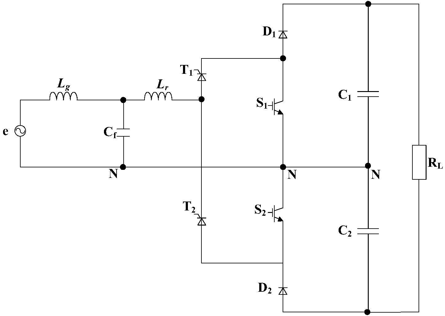
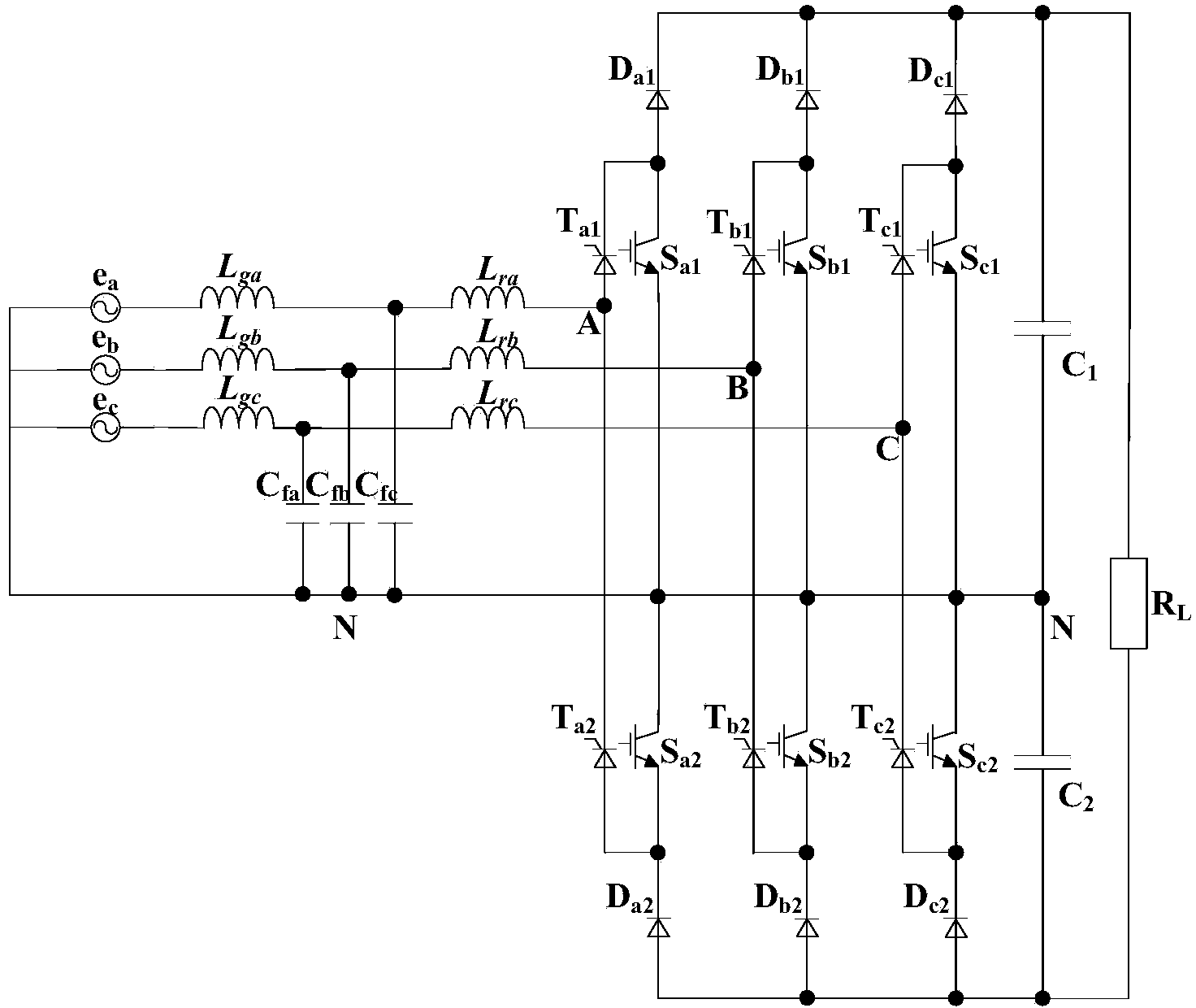
[0026] The circuit topology structure of a PWM rectifier provided by the invention is divided into a single-phase PWM rectifier and a three-phase four-wire PWM rectifier. Such as figure 1 As shown, the circuit topology is a single-phase PWM rectifier, including the grid-side filter inductor L g , Converter side filter inductance L r , AC filter capacitor C f , the first thyristor T 1 , the second thyristor T 2 , the first diode D 1 , the second diode D 2 , the first full-control switch switch S 1 , the second full-control switch switch S 2 , the first capacitance C 1 , the second capacitance C 2 , load R L and the neutral line N, the fully controlled switch can be IGBT, IGCT and power field effect transistor (Power MOSFET). Grid side filter inductance L g One end is connected to the power grid, and the other end is connected to the converter side fil...
PUM
 Abstract
Description
Claims
Application Information