
A microfluidic chip and detection device suitable for PCR or HRM detection and analysis

A microfluidic chip and detection device technology, applied in enzymology/microbiology devices, biochemical cleaning devices, specific-purpose bioreactors/fermenters, etc., can solve the problem of different functions of sealing valves, cumbersome and time-consuming operations , cavity reagent overflow and other problems, to achieve the effect of fast heating speed, high fluorescence collection efficiency, and no mutual pollution

Active Publication Date: 2016-07-06
HEFEI INSTITUTES OF PHYSICAL SCIENCE - CHINESE ACAD OF SCI +1
View PDF6 Cites 0 Cited by
  • Summary
  • Abstract
  • Description
  • Claims
  • Application Information

AI Technical Summary

Problems solved by technology

Commonly used sealing forms include pneumatic micro-valve, which is easy to integrate, can realize array sealing, and is easy to operate, but the micro-valve is easy to leak when heated; adopting micro-pillar plug type sealing has good sealing effect, but for array reaction There are many cavities, and the operation is cumbersome and time-consuming; the screw type seal is used, and the sealing situation is the same as that of the micro-plunger type; the liquid curing type seal is used, and the fluid flows into the seal, which may easily cause the cavity reagent to overflow and cause mutual interference. Miscellaneous interference; the wax melting type seal is adopted, and the melting point of the substance is higher than that of water, but this kind of sealing also has the overflow of the reagents in the reaction chamber, causing mutual interference; the composite method is adopted, that is, the sample injection is a kind of valve, and the reaction in the chamber Using another valve seal, this operation is too cumbersome
The design and manufacture of the microvalve are closely related to the use of the chip. The functions of the injection valve and the sealing valve of the cavity reaction are not the same. Using ordinary design thinking to design the microvalve, it is difficult to achieve both.

Method used


Image

  • A microfluidic chip and detection device suitable for PCR or HRM detection and analysis
  • A microfluidic chip and detection device suitable for PCR or HRM detection and analysis
  • A microfluidic chip and detection device suitable for PCR or HRM detection and analysis

Examples


example 1

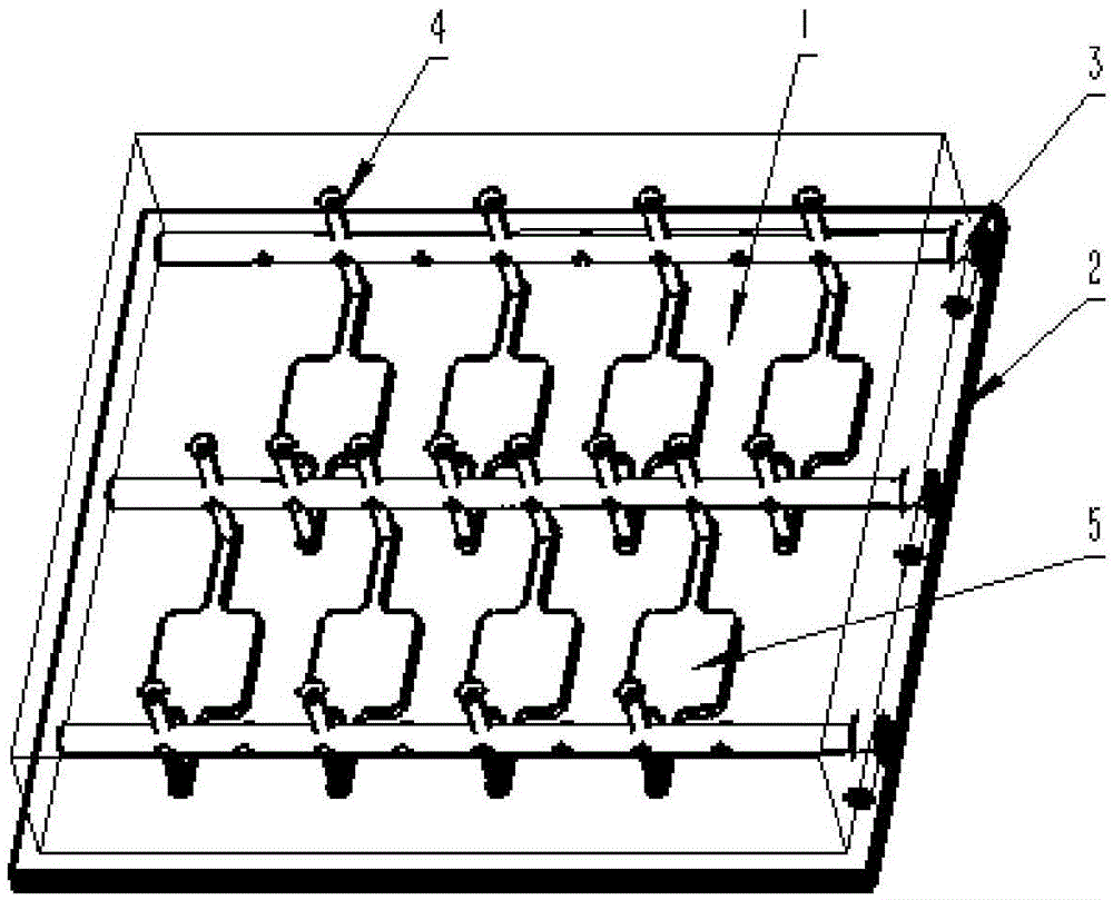
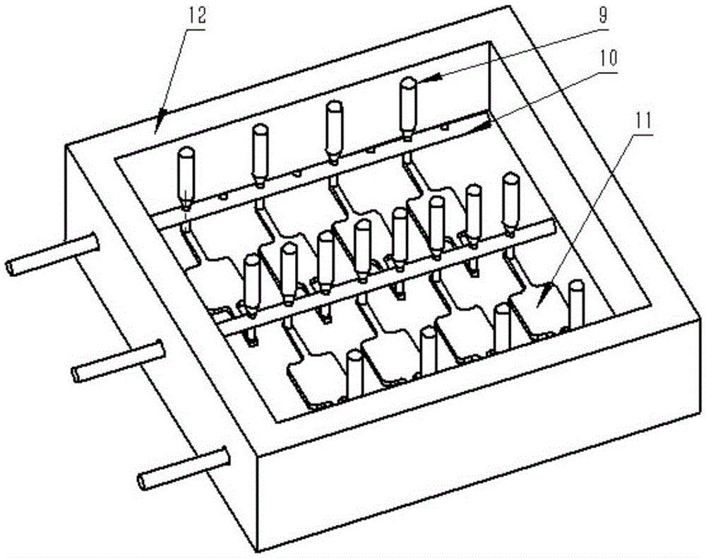
[0048] The cavity size of the combined mold is 33mm×32mm×7mm, the volume of the raised reaction chamber is 12uL, double-row structure, 4 in each row, a total of 8 reaction chambers, the channel is 0.4mm, the diameter of the mold cross column is 1mm, the mold The hole on the cross column is 0.3mm, the diameter of the mold column is 0.3mm, inject PDMS glue into the mold, heat and solidify, remove the mold column, take out the mold cross column, and fall off from the template to obtain a microchannel and reaction chamber. body substrate. The PDMS substrate and the 50mm×40mm glass substrate were cleaned by plasma to modify the surface and bonded to form a microfluidic chip. A 1.2mm rotating long rod with a handle is inserted into the die cross-column hole of the chip. The micro-holes on the mold cross-column are 0.3mm in size, and the micro-holes correspond to the channels generated by the mold post. At this time, the microfluidic chip is processed for biocompatibility, high temp...

example 2

[0050]The combined mold cavity size is 22mm×25mm×7mm, the volume of the raised reaction cavity is 20uL, single-row structure, 2 reaction chambers, the channel is 0.4mm, the diameter of the mold cross column is 1mm, and the hole on the mold cross column is 0.3mm, the diameter of the mold column is 0.3mm, inject PDMS glue into the mold, heat and cure, remove the mold column, take out the mold cross column, and fall off the template to obtain a substrate with microchannels and reaction chambers. The PDMS substrate and the 25mm×30mm glass substrate were cleaned by plasma to modify the surface and bonded to form a microfluidic chip. A 1.2mm rotating long rod with a handle is inserted into the die cross-column hole of the chip. The micro-holes on the mold cross-column are 0.3mm in size, and the micro-holes correspond to the channels generated by the mold post. At this time, the microfluidic chip is processed for biocompatibility, high temperature sterilization and other related proc...


PUM

PropertyMeasurementUnit
melting pointaaaaaaaaaa

Abstract

The invention discloses a micro-fluidic chip and a detecting device suitable for PCR (polymerase chain reaction) or HRM (high resolution melting) detection analysis. A micro pipeline and an array reaction chamber base plate form a combined mould, a micro-fluidic base chip is generated by virtue of an injection molding method, the micro-fluidic chip is formed by virtue of plasma cleaning and glass bonding; a rotary rod with a handle and a duct is transversely embedded in an outward channel center of the chip to form a rotary valve; the handle rotates to disconnect the duct to control on-off and sealing of multi-reaction-chamber sampling, so that physical isolation between reaction chambers is realized, the sealing performance is good, and cross contamination does not exist, and thus, a plurality of samples can be detected at the same time. The micro-fluidic chip disclosed by the invention not only can be used for independent PCR detection or HRM detection, but also can be used for performing PCR detection and then performing HRM detection without any change in a combined manner, so that the multi-functionalization of detection is realized.

Description

technical field [0001] The invention relates to the technical field of microfluidic chips, in particular to a microfluidic chip and a detection device suitable for PCR or HRM detection and analysis. Background technique [0002] As a new micro-nano analysis technology platform, the microfluidic chip integrates the basic operation units such as sample preparation, separation and detection involved in the fields of biology and chemistry into a chip of a few square centimeters. The characteristics and advantages of flexible combination and large-scale integration on the small platform controlled by the system. Microfluidic chips have the advantages of saving space and reagents, small heat capacity, fast heating and cooling rates, and easy integration. The main feature of a microfluidic chip on a device is that its effective structure for containing fluids (including channels, reaction chambers, and certain other functional components) is micron-scale in at least one dimension....

Claims


Application Information

Patent Timeline
Patent Type & Authority Patents(China)
IPC IPC(8): C12M1/00C12M1/38C12M1/34
CPCB01L7/52B01L2300/0627B01L2300/0819B01L2300/1805
Inventor 赵树弥朱灵邓国庆王贻坤朱灿灿张龙李志刚刘勇王安
Owner HEFEI INSTITUTES OF PHYSICAL SCIENCE - CHINESE ACAD OF SCI
Learn More