
A method and device for catalytic hydrogen production suitable for hydrogen energy vehicles

A technology for automobiles and catalysts, which is applied in the field of catalytic hydrogen production by liquid organic hydrides. It can solve the problems of reduced dehydrogenation effects, expensive catalysts, and bulky reaction devices, so as to reduce reaction costs, simplify the hydrogen production process, and improve reaction efficiency. Effect

Inactive Publication Date: 2016-08-24
ZHEJIANG UNIV
View PDF2 Cites 0 Cited by
  • Summary
  • Abstract
  • Description
  • Claims
  • Application Information

AI Technical Summary

Problems solved by technology

From a thermodynamic point of view, the catalytic dehydrogenation of liquid organic hydrides is an endothermic reaction, and high temperature is conducive to the occurrence of dehydrogenation reaction, while the highest temperature of the catalyst in the liquid dehydrogenation reaction can only reach the boiling point of the reactant, which is not good for the reaction.
From a kinetic point of view, the catalytic dehydrogenation of liquid organic hydrides is a reversible reaction, and the reverse reaction is easy to occur under the conditions of the liquid dehydrogenation reaction, resulting in a decrease in the dehydrogenation effect.
Under the conditions of traditional gaseous dehydrogenation reaction technology, the use of Pt, Pd, Rh and other noble metals and their doped mixed catalysts can achieve good dehydrogenation effect, but the catalyst is easy to coke and deactivate, and the continuity of the reaction is not good. The catalyst is expensive and the reaction device is bulky, which is not suitable for the vehicle application of hydrogen vehicles

Method used


Image

  • A method and device for catalytic hydrogen production suitable for hydrogen energy vehicles

Examples


Embodiment 1

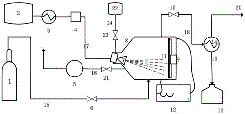
[0027]Take 12 g of Raney nickel catalyst, wash 3 times with absolute ethanol to replace the moisture therein, and press the catalyst into a circular sheet, and fix it on the rotating electromagnetic heating plate at the bottom of the reactor; turn on the vacuum pump to turn the reactor Vacuumize, turn off the vacuum pump, open the nitrogen bottle, feed nitrogen into the reactor, turn on the rotating electromagnetic heating plate under the protection of nitrogen, and slowly raise the temperature of the catalyst at a rate of 10°C / min to remove the bound moisture and Anhydrous ethanol, when the temperature rises to 160°C, the catalyst has been dried, at this time stop nitrogen, open the liquid organic hydride cooler to cool the cyclohexane to 6°C; set the dehydrogenation reaction temperature to 381°C, and react Electromagnetically heat the bottom of the reactor to the dehydrogenation reaction temperature, turn on the temperature control speed changer, keep the rotation speed of th...

Embodiment 2

[0029] Take 20 g of the catalyst Raney nickel, wash 3 times with absolute ethanol to replace the water therein, and press the catalyst into a circular sheet, and fix it on the rotating electromagnetic heating plate at the bottom of the reactor; turn on the vacuum pump to turn the reactor Vacuumize, turn off the vacuum pump, open the nitrogen bottle, feed nitrogen into the reactor, turn on the rotating electromagnetic heating plate under the protection of nitrogen, and slowly raise the temperature of the catalyst at a rate of 10°C / min to remove the bound moisture and Anhydrous ethanol, when the temperature rises to 160°C, the catalyst has been dried, at this time stop nitrogen, open the liquid organic hydride cooler to cool the cyclohexane to 6°C; set the dehydrogenation reaction temperature to 363°C, and react Electromagnetically heat the bottom of the reactor to the dehydrogenation reaction temperature, turn on the temperature control variable speed instrument, keep the rotati...

Embodiment 3

[0031] Take 20 g of the catalyst Raney nickel, wash 3 times with absolute ethanol to replace the water therein, and press the catalyst into a circular sheet, and fix it on the rotating electromagnetic heating plate at the bottom of the reactor; turn on the vacuum pump to turn the reactor Vacuumize, turn off the vacuum pump, open the nitrogen bottle, feed nitrogen into the reactor, turn on the rotating electromagnetic heating plate under the protection of nitrogen, and slowly raise the temperature of the catalyst at a rate of 10°C / min to remove the bound moisture and Anhydrous ethanol, when the temperature rises to 160°C, the catalyst has been dried, at this time, the nitrogen flow is stopped, and the liquid organic hydride cooler is opened to cool the cyclohexane to 6°C; the dehydrogenation reaction temperature is set to 371°C, and the reaction Electromagnetically heat the bottom of the reactor to the dehydrogenation reaction temperature, turn on the temperature control variabl...


PUM


Abstract

The invention discloses a catalytic hydrogen production method and device suitable for a hydrogen energy automobile. The method disclosed by the invention specifically comprises the following steps: electromagnetically heating to dry a catalyst under nitrogen protection, stopping introduction of nitrogen and starting a liquid organic hydride cooler; starting a temperature control rheometer, maintaining the rotating speed of a rotary electromagnetic heating disc, and after the catalyst is stabilized at the reaction temperature, spraying, atomizing and feeding the liquid organic hydride intermittently; and condensing, separating and discharging the product hydrogen. According to the method and device disclosed by the invention, hydrogen production reaction conditions are uniformly designed and optimized to obtain the optimal reaction conditions. According to the method and device disclosed by the invention, a noble metal catalyst is replaced by cheap raney nickel, so that the reaction cost is lowered, and a carbon deposition deactivated catalyst can be regenerated by eliminating carbon with water vapor. A spraying and atomizing feeding method is adopted, the rotary electromagnetic heating is arranged, the surface temperature return time of the catalyst is fully utilized, and dehydrogenation reaction is carried out under a wet-dry multiphase reaction condition, so that the reaction efficiency is improved. No carrier gas is adopted, and the produced hydrogen is high in purity and free of being re-separated, so that the method and device are suitable for the hydrogen energy automobile.

Description

technical field [0001] The present invention relates to the field of catalytic hydrogen production using liquid organic hydrides, in particular to a method for producing hydrogen by continuously dehydrogenating liquid organic hydrides using a catalyst after optimization of uniform design conditions under "wet-dry" multiphase reaction conditions and device. Background technique [0002] As an ideal new energy source, hydrogen energy plays an important role in today's energy industrial revolution, especially in the use of hydrogen energy vehicles. As a clean energy source, hydrogen energy has the highest energy density among all energy sources. A highly efficient energy carrier. Therefore, the status of hydrogen energy in the future energy economy is widely optimistic, especially when people are trying to reduce the climate impact of global warming caused by human activities and the status quo of excessive dependence on fossil fuels, the use of hydrogen energy is particularly...

Claims


Application Information

Patent Timeline
Patent Type & Authority Patents(China)
IPC IPC(8): C01B3/22
CPCY02P20/584
Inventor 徐国华平浩梁寇智宁朱志文吴富英宋林支尊欧
Owner ZHEJIANG UNIV
Learn More