Composite cathode for plasma spray gun

A composite cathode and plasma technology, applied in the direction of plasma, electrical components, etc., can solve the problem of easy ablation of the cathode, and achieve the effects of not easy to ablate, improve processing efficiency, and large heat dissipation area

Inactive Publication Date: 2015-02-04
周开根
View PDF9 Cites 6 Cited by
  • Summary
  • Abstract
  • Description
  • Claims
  • Application Information

AI Technical Summary

Problems solved by technology

[0005] The purpose of the present invention is to overcome the shortcoming that the cathode of the existing plasma spray gun is easily ablated, and to provide a composite cathode for the plasma spray gun, which is suitable for flushing and cooling, so that the cathode is not easy to be ablated, so as to prolong the plasma spray gun life cycle, improve production efficiency and save production costs

Method used


Image

  • Composite cathode for plasma spray gun
  • Composite cathode for plasma spray gun
  • Composite cathode for plasma spray gun

Examples


Embodiment 1

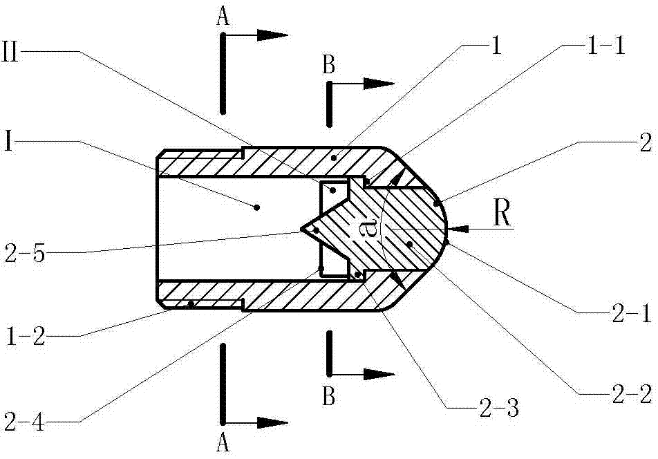
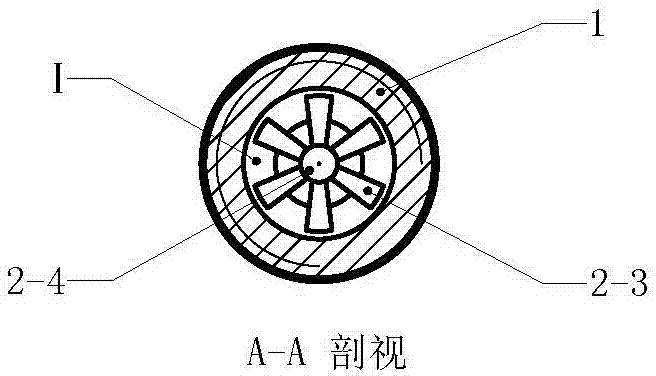
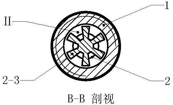
[0015] Example 1 figure 1 In the embodiment shown, a composite cathode for a plasma torch is composed of a cathode casing (1) and a cathode head (2), wherein the cathode casing (1) is a hollow rotary body structure, and the cathode casing (1 ) has a limited step ring (1-1) on the inside of the front end, and a mounting screw (1-2) on the outside of the rear of the cathode sleeve (1), and the front end of the cathode sleeve (1) is a frustum of cone structure that shrinks from the back to the front , the conical angle (a) is 60°-120°; the cathode head (2) is embedded in the inner space at the front of the cathode sleeve (1), and the front end of the cathode head (2) protrudes from the cathode sleeve (1), The front end of the cathode head (2) is a circular arc surface, the radius (R) of the arc at the end of the cathode head is 10 mm, the embedded section (2-2) of the cathode head (2) is a cylindrical structure, and the insertion of the cathode head (2) There is a flange (2-3)...

Embodiment 2

[0016] Example 2 Figure 4 The embodiment shown is the application of the present invention on the plasma torch, and the plasma torch is mainly composed of a back seat (8), a composite cathode, an insulating gun frame (5), an anode sleeve (4) and an anode (3), wherein , the structure of the composite cathode is the same as that in the first implementation, and will not be repeated; the rear seat (8) is a hollow rotary body structure, and there is a screw groove (8-4) on the inner side of the front part of the rotary body of the rear seat (8). There is connecting thread (8-5) on the outside of the front part of the rear seat (8), and the composite cathode is installed on the screw groove (8-4) at the front part of the rotary body of the rear seat (8), and the rotation of the rear seat (8) There is a guide tube (8-2) in the body structure, and the guide tube (8-2) extends into the cooling cavity (I) in the composite cathode and is close to the guide cone (2-5), and the guide t...


PUM


Abstract

A composite cathode for a plasma spray gun relates to a cathode structure of the plasma spray gun and is formed by a cathode sleeve and a cathode head. The cathode sleeve is in a hollow rotation body structure; the cathode head is embedded to the inner space at the front portion of the cathode sleeve; the front end of the cathode head extends out of the cathode sleeve; the embedded section of the cathode head is in a cylinder structure; the inner space of the cathode sleeve at the back end of the cylinder structure forms a cooling cavity; the back end of the cylinder structure of the cathode head is a flow guidance cone which is reduced gradually backwards; the axis of the flow guidance cone is overlapped with the axis of the embedded section; the circumference of the flow guidance cone is provided with a plurality of cooling rib plates; the cooling rib plates and the cathode head are integrated in a radial arrangement manner; the flow guidance cone and the cooling rib plates are arranged in the cooling cavity; and spaces between the plurality of cooling rib plates form cooling branch grooves. According to the composite cathode, the cathode is divided into two components to carry out processing, thereby making production simple, improving processing efficiency of the components, and saving material cost; and the composite cathode is suitable for a washing cooling mode, and heat at the head portion of the cathode can be removed quickly.

Description

technical field [0001] The invention relates to plasma equipment, in particular to a cathode structure of a plasma torch. Background technique [0002] At present, plasma technology has been widely used, industrially used in plasma ignition, plasma spraying, metal smelting, plasma heating to manufacture nanomaterials, cutting, waste incineration and waste treatment, etc. The plasma treatment method is very different from the general method. Plasma is a state formed under the ionosphere or discharge phenomenon. With the discharge phenomenon, excited atoms, excited molecules, dissociated atoms, free atomic groups, Active chemicals of groups of atoms or molecular ions and their reactions resulting from collisions with other chemicals. In the plasma generator, the discharge effect causes the working gas molecules to lose the outer electrons and form an ion state, which generates high temperature through mutual collision, and the temperature can reach more than tens of thousands...

Claims


Application Information

Patent Timeline
Patent Type & Authority Applications(China)
IPC IPC(8): H05H1/28H05H1/34
Inventor 周开根
Owner 周开根
Why Eureka
Try Eureka