Photovoltaic thin-film solar modules and method for producing such thin-film solar modules

A solar module and solar cell technology, applied in photovoltaic power generation, final product manufacturing, sustainable manufacturing/processing, etc., can solve problems such as limited final design of thin-layer solar modules

Active Publication Date: 2015-02-04
NICE SOLAR ENERGY GMBH
View PDF7 Cites 7 Cited by
  • Summary
  • Abstract
  • Description
  • Claims
  • Application Information

AI Technical Summary

Problems solved by technology

Even when all method optimization and material optimization are concerned, it is always strongly limited to the final design of thin-film solar modules set for sale

Method used


Image

  • Photovoltaic thin-film solar modules and method for producing such thin-film solar modules
  • Photovoltaic thin-film solar modules and method for producing such thin-film solar modules
  • Photovoltaic thin-film solar modules and method for producing such thin-film solar modules

Examples


Embodiment Construction

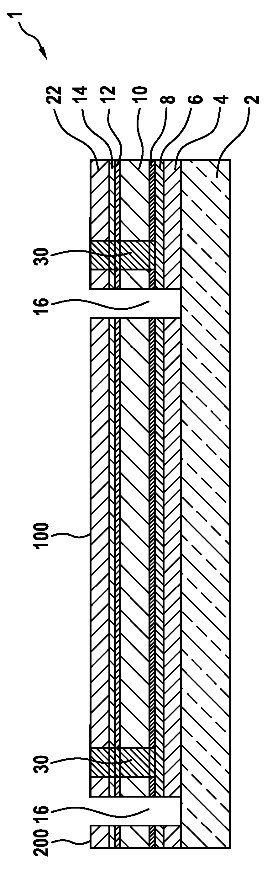
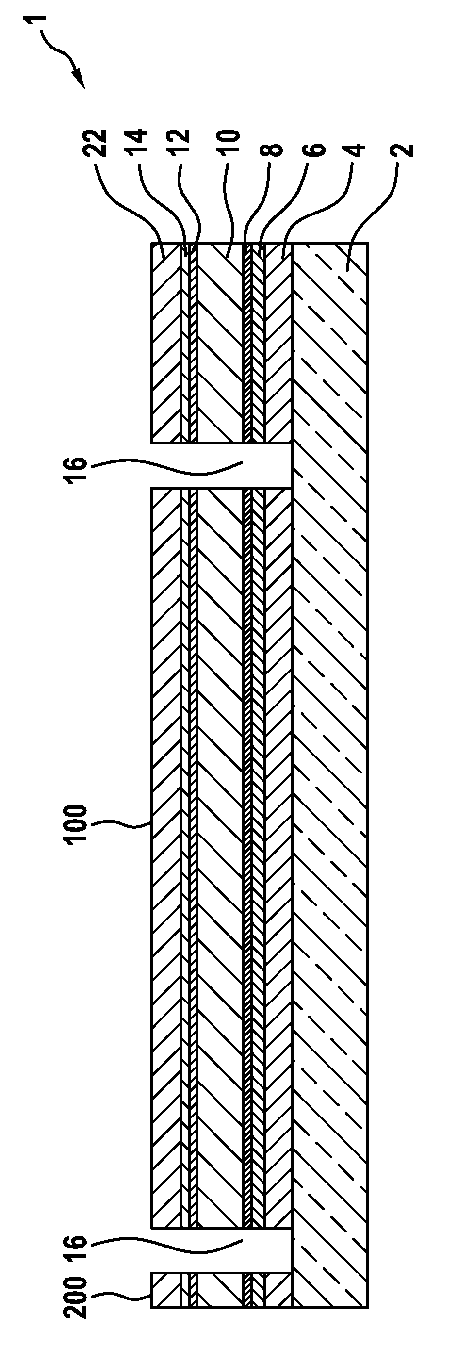
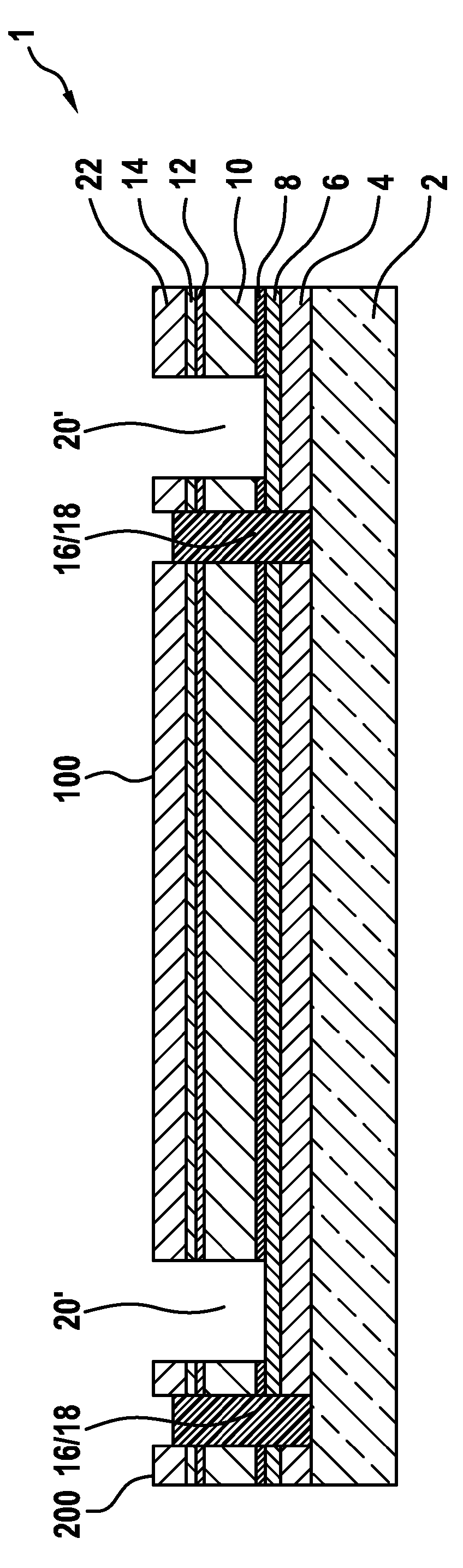
[0145] derived from figure 1A schematic cross-sectional view of an intermediate manufacturing stage of the inventive thin-film solar module 1 . A bulk back electrode layer 4 , for example composed of molybdenum, is present on the glass substrate 2 by means of thin-layer deposition. Adjacent to it is placed a bidirectionally reflective barrier layer 6, for example composed of TiN or ZrN, which can likewise be obtained by thin-layer deposition. In the embodiment shown, an ohmic contact layer 8 consisting of a metal chalcogenide such as molybdenum selenide is placed on this barrier layer 6 . As already generally stated above, the contact layer can be obtained in different ways and methods. In one development, molybdenum selenide is sputtered, for example, from a molybdenum selenide target. Alternatively, a metal layer can be applied first, which is then converted to the corresponding metal chalcogenide before and / or during the formation of the semiconductor absorber layer. In...


PUM


Abstract

The invention relates to photovoltaic thin-film solar modules, comprising in a first embodiment, particularly in the following order: at least one substrate layer; at least one rear electrode layer, particularly directly contacting the substrate layer; at least one conductive barrier layer, particularly directly contacting the rear electrode layer and / or the substrate layer; at least one contact layer, particularly an ohmic contact layer, particularly directly contacting the barrier layer; at least one semiconductor absorber layer, particularly a chalcopyrite or kesterite semiconductor absorber layer, particularly directly contacting the contact layer; optionally at least one first buffer layer, particularly directly contacting the semiconductor absorber layer and containing or substantially made of CdS or a CdS-free layer, particularly containing or made substantially of Zn(S, OH) or In2S3; and / or optionally at least one second buffer layer, particularly directly contacting the semiconductor absorber layer or the first buffer layer and containing or substantially made of intrinsic zinc oxide and / or high-resistance zinc oxide; and at least one transparent front electrode layer, particularly directly contacting the semiconductor absorber layer, the first buffer layer and / or the second buffer layer and particularly containing or substantially made of n-doped zinc oxide. Said thin-film solar modules further comprise: spaced-apart first structuring separation trenches filled with at least one insulating material, said trenches separating adjacent solar cells from one another down to the substrate layer; spaced-apart second structuring separation trenches filled or provided with at least one conductive material, said trenches extending to the contact layer or to the rear electrode layer or to the barrier layer, particularly to the barrier layer and each being adjacent to a filled first structuring separation trench; spaced-apart third structuring separation trenches, which extend to the contact layer or to the rear electrode layer or to the barrier layer, particularly to the barrier layer, and are each adjacent to a second structuring trench on the other side of the first structuring trench to which the second structuring trench is adjacent; and at least one conductive bridge from second structuring trenches filled with a conductive material or furnished with such a material to the front electrode layer of the adjacent solar cell, across adjacent first structuring separation trenches filled with insulating material. The invention further relates to a method for producing such thin-film solar modules.

Description

technical field [0001] The invention relates to a photovoltaic thin-film solar module and to a method for producing such a thin-film solar module. Background technique [0002] Photovoltaic solar modules have long been known and are also commercially available. Suitable solar modules include crystalline and amorphous silicon solar modules on the one hand and so-called thin-film solar modules on the other hand. Such thin-film solar modules are based, for example, on the use of so-called chalcopyrite semiconductor absorbers, eg Cu(In,Ga)(Se,S) systems, and are complex multilayer systems. In the case of these thin-film solar modules, a molybdenum back electrode layer is usually placed on a glass substrate. In a method variant, the molybdenum rear electrode layer is provided with a thin layer of a precursor metal comprising copper and indium and optionally gallium, and is then heated at elevated temperature in the presence of hydrogen sulfide and / or hydrogen selenide is trans...

Claims


Application Information

Patent Timeline
Patent Type & Authority Applications(China)
IPC IPC(8): H01L27/142H01L31/0392H01L31/0749H01L31/032H01L31/18
CPCH01L31/03923H01L31/0749H01L31/0326H01L31/0465Y02E10/541Y02E10/543Y02P70/50H01L31/022441H01L31/022483H01L31/0323H01L31/0327H01L31/0508H01L31/1828H01L31/0475
Inventor V.普罗布斯特
Owner NICE SOLAR ENERGY GMBH
Why Eureka
Try Eureka