

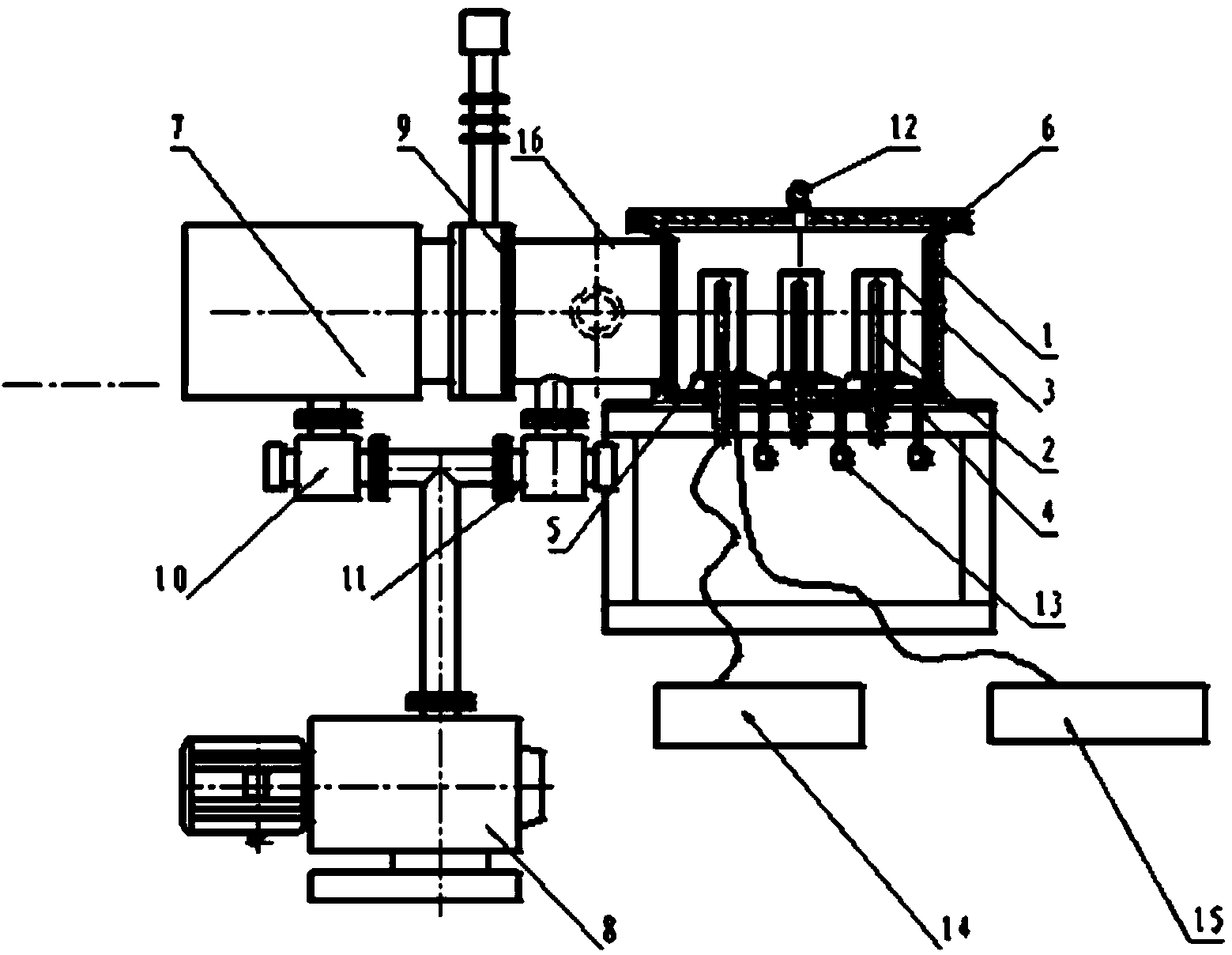
Diode sputtering coating equipment used for coating inner wall of vacuum cup
A technology of sputtering coating and coating equipment, which is applied in the field of vacuum cups, and can solve problems such as inability to form industrialization, differences in coating quality, and increased production costs.
- Summary
- Abstract
- Description
- Claims
- Application Information
AI Technical Summary
Problems solved by technology
Method used
Image

Examples
Embodiment 1
[0033] Use this diode sputtering coating equipment for coating the inner wall of the vacuum cup to plate nano-silver coating on the inner wall of the stainless steel vacuum cup.
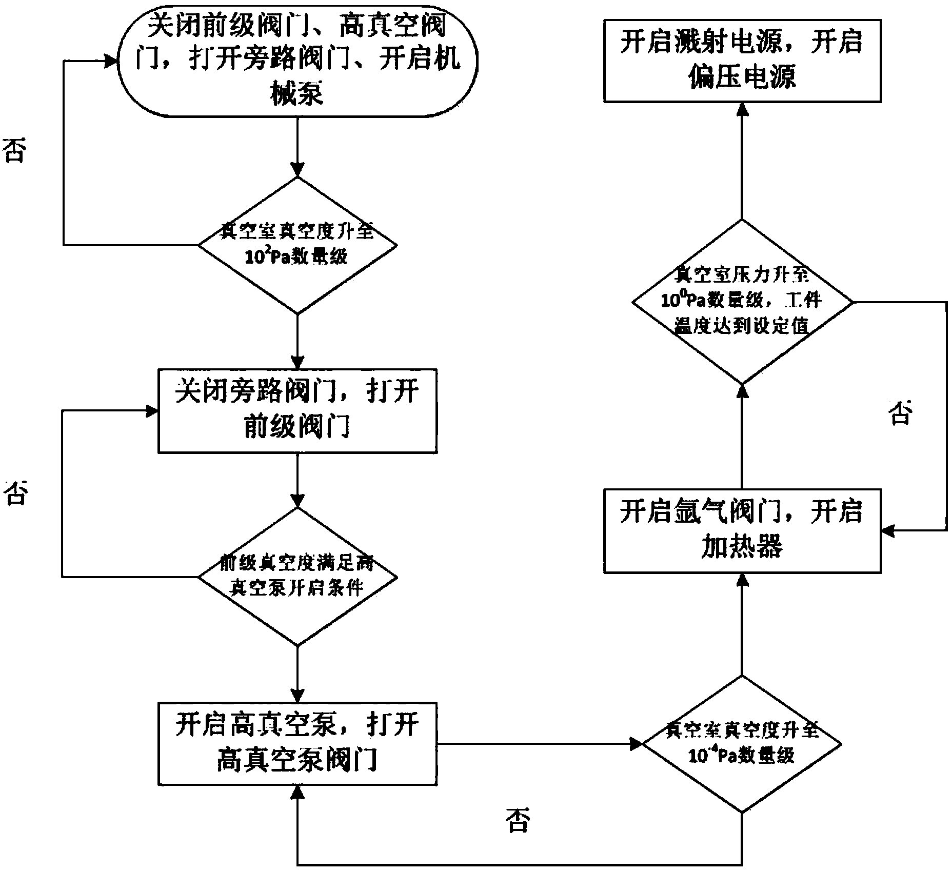
[0034] First, ultrasonically clean the inner wall of the stainless steel vacuum cup and the silver electrode and dry them. At the same time, clean the vacuum chamber and vacuum system of the equipment, and place the vacuum cup and silver electrode in the vacuum chamber. Start the vacuum system to evacuate until the vacuum degree of the vacuum chamber rises to 10 -4 Pa order of magnitude; open the heater vacuum cup workpiece to 200 and open the argon valve to feed argon until the vacuum chamber pressure is 10 0 Pa order of magnitude; turn on the sputtering power supply and adjust the voltage to about 4KV, turn on the bias power supply and adjust the voltage to about 100V. The coating time is 20~60 minutes.
Embodiment 2
[0036] The nano-copper alloy coating is plated on the inner wall of the stainless steel vacuum cup by using the diode sputtering coating equipment for coating the inner wall of the vacuum cup.
[0037] First, ultrasonically clean the inner wall of the stainless steel vacuum cup and silver electrodes and dry them. At the same time, clean the vacuum chamber and vacuum system of the equipment, and place the vacuum cup and copper alloy electrodes in the vacuum chamber. Start the vacuum system to evacuate until the vacuum degree of the vacuum chamber rises to 10 -4 Pa order of magnitude, open the heater vacuum cup workpiece to 300 and open the argon valve to feed argon until the vacuum chamber pressure is 10 0 Pa order of magnitude, turn on the sputtering power supply and adjust the voltage to about 6KV, turn on the bias power supply and adjust the voltage to about 150V. The coating time is 10~20 minutes.
[0038] The technology used in the present invention is the two-pole sputt...
PUM
 Abstract
Description
Claims
Application Information