Eureka AIR delivers breakthrough ideas for toughest innovation challenges, trusted by R&D personnel around the world.

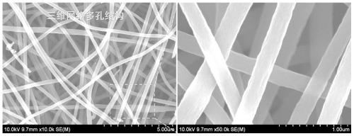
Carbon nanofiber, diffusion layer, membrane electrode, fuel cell and preparation method and application thereof

A carbon nanofiber and diffusion layer technology, which is applied in fuel cells, battery electrodes, fiber chemical characteristics, etc., can solve the problems of active site deactivation, large free path of material diffusion, and small pore volume

Active Publication Date: 2020-08-25
SHANGHAI ELECTRICGROUP CORP
View PDF16 Cites 0 Cited by
  • Summary
  • Abstract
  • Description
  • Claims
  • Application Information

AI Technical Summary

Problems solved by technology

[0004] The present invention provides a carbon nanofiber, diffusion layer, membrane electrode, Fuel cell and its preparation method and application
[0005] The present invention aims at constructing a local high-efficiency proton transport channel and a water molecule conduction channel at the three-phase reaction interface in the catalytic layer, thereby improving the proton, O 2 The reactants are sufficient, and the water flooding phenomenon of the catalytic layer is suppressed, and the problem of active site deactivation is solved, so as to improve the performance of the fuel cell membrane electrode

Method used


Image

  • Carbon nanofiber, diffusion layer, membrane electrode, fuel cell and preparation method and application thereof
  • Carbon nanofiber, diffusion layer, membrane electrode, fuel cell and preparation method and application thereof
  • Carbon nanofiber, diffusion layer, membrane electrode, fuel cell and preparation method and application thereof

Examples


Embodiment 1

[0079] 1. Preparation of carbon nanofibers

[0080] S1. First, weigh 2g of polyacrylonitrile (PAN) powder, and dissolve it in 30g of DMF solution, with a mass fraction of 6.25wt%. Stir on a heated magnetic stirrer for 3 hours, control the temperature at 60°C, fully dissolve, and form a solution with PAN spinning precursor;

[0081] Transfer the spinning solution to the syringe, fix it on the electrospinning machine, set the spinning environment temperature to 45°C, control the humidity below 30% to 35%, the spinning voltage to 19kV, and the spinning solution supply speed to 0.10mm / min, wrap the cut aluminum foil on the drum, close the protection door of the spinning box, turn on the high-voltage power supply, and carry out double-nozzle electrospinning, adjust the drum collection speed to 80rpm, until the spinning liquid is consumed, and end the electrospinning.

[0082] S2. Take down the receiver, collect the polymer fiber cloth, and place it in a vacuum oven at 60° C. for ...

Embodiment 2

[0089] 1. Preparation of carbon nanofibers

[0090] S1. First, weigh 2 g of polyvinylpyrrolidone (PVP) powder, and dissolve it in 23 g of DMF solution, with a mass fraction of 8 wt%. Stir on a heated magnetic stirrer for 4 hours, control the temperature at 90°C, fully dissolve, and form a spinning solution with PVP;

[0091] Transfer the spinning solution to the syringe, fix it on the electrospinning machine, set the spinning environment temperature to 45°C, control the humidity at 30% to 60%, the spinning voltage to 17kV, and the spinning solution supply speed to 0.06mm / min , Wrap the cut aluminum foil on the drum, close the protection door of the spinning box, turn on the high-voltage power supply, perform double-nozzle electrospinning, adjust the drum collection speed to 80rpm, until the spinning solution is consumed.

[0092]S2. Take down the receiver, collect the polymer fiber cloth, and place it in a vacuum oven at 60° C. for drying.

[0093] S3. Arrange the dried fibe...

Embodiment 3

[0099] With polyacrylonitrile (PAN) and polyethylene oxide (PEO) blend (mass ratio is 1:1) to replace polyacrylonitrile (PAN) in embodiment 1, other conditions are identical with embodiment 1, obtain Black solid carbon nanofiber. The prepared carbon nanofibers were used to prepare a diffusion layer, and the preparation method was the same as in Example 1.


PUM


Abstract

The invention discloses a carbon nanofiber, a diffusion layer, a membrane electrode, a fuel cell and a preparation method and application thereof. The preparation method of the carbon nanofiber comprises the following steps: S1, carrying out electrostatic spinning on a spinning solution and then carrying out drying, wherein the spinning solution comprises a polymer and a solvent, the mass fractionof the polymer in the spinning solution being 6-10%, the polymer comprising a nitrogen-containing polymer, the nitrogen-containing polymer being one or more of polyacrylonitrile, polyvinylpyrrolidone, polyacetamide and polyaniline, and the drying temperature being 60 to 80 DEG C; and S2, carrying out high-temperature carbonization, wherein the carbonization temperature is 750-950 DEG C. The diffusion layer prepared from the carbon nanofiber is large in pore volume, small in substance diffusion free path and high in substance transmission capacity.

Description

technical field [0001] The invention relates to a carbon nanofiber, a diffusion layer, a membrane electrode, a fuel cell and a preparation method and application thereof. Background technique [0002] Water management plays an important role in proton exchange membrane fuel cells (PEMFC), because at the cathode side of PEMFC, H + and O 2 The reaction produces water, which diffuses through the catalytic layer into the diffusion layer. If the water generated by the cathode cannot be discharged in time, excess water will accumulate in the diffusion layer. In severe cases, the catalytic layer will be flooded, covering the active sites, and increasing the activation polarization. At the same time, the existence of a large amount of water hinders the effective diffusion of gas and increases Concentration polarization; it will also lead to uneven distribution of reaction gas in each reaction unit, insufficient gas on the reaction interface, and reduce the overall performance of t...

Claims


Application Information

Patent Timeline
IPC IPC(8): H01M4/88H01M4/92H01M8/1004D01F9/21D01F9/22D01F9/24
CPCH01M4/8807H01M4/926H01M8/1004D01F9/22D01F9/21D01F9/24Y02E60/50
Inventor 朱星烨杨敏李晓琳汪聪敏季文姣黄腾达
Owner SHANGHAI ELECTRICGROUP CORP
Why Eureka
Eureka Blog
Learn More