Image-guided puncture device

A device and imaging technology, applied in the field of medicine, can solve the problems of undiscovered technical reports of new image-guided puncture devices, in the preclinical research stage, and high surgical success rate

Inactive Publication Date: 2015-04-29
尚鸣异
View PDF4 Cites 4 Cited by
  • Summary
  • Abstract
  • Description
  • Claims
  • Application Information

AI Technical Summary

Problems solved by technology

[0045] ⑤High operation success rate and low mortality rate; according to relevant statistics, the success rate of interventional therapy is as high as 90%, while the mortality rate is almost zero
[0060] China's research and application status: DCbead has not yet been approved to enter the Chinese market, but the research on drug-loaded microspheres has always been one of the hot spots in the field of pharmaceuticals and interventional radiology in China. Many types have been developed, including 5-fluorouracil polylactic acid microspheres, Doxorubicin sodium alginate microspheres, ion-exchange microspheres containing pingyangmycin, cisplatin microspheres, and compound zedoary oil microspheres containing traditional Chinese medicine ingredients have initially shown certain curative effects in animal experiments, but they are all in the In the preclinical research stage, there is still a big gap from the actual clinical application
[0061] 2. Radioembolization
The disadvantage is that the level of tumor ablation therapy in various regions of China is not the same, lack of standardization, and there is a tendency to blindly expand indications; in addition, there is still a lack of multi-center prospective controlled studies comparing it with other treatments
According to literature search, so far, no technical reports on new image-guided puncture equipment have been found.

Method used


Image

  • Image-guided puncture device
  • Image-guided puncture device
  • Image-guided puncture device

Examples


Embodiment 1

[0155] Embodiment 1, a practical structure of image-guided puncture equipment

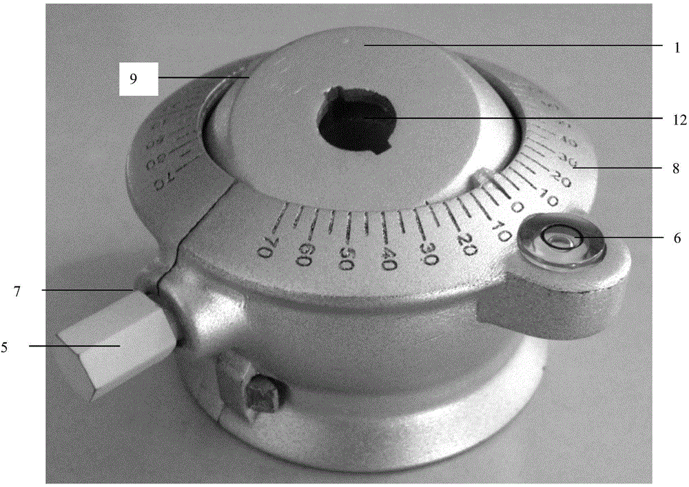
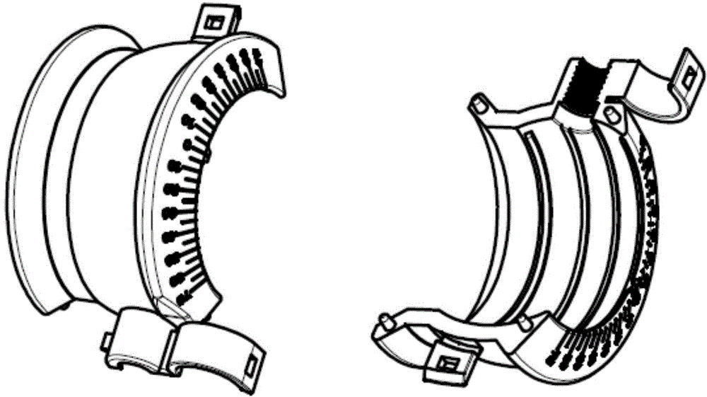
[0156] The device consists of three parts: a guiding ball (1), a universal shaft frame (2), and a puncture sleeve (3). The guiding ball (1) is embedded in the universal shaft frame (2) and can rotate freely at 360 degrees; The sleeve (3) is inserted into the hole (12) at the center of the guide sphere (1) for relative fixation;

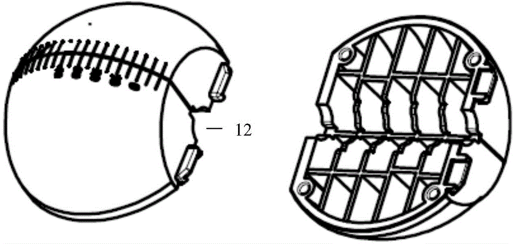
[0157] ①The structure of the guiding sphere (1) is as follows: two hemispheres (11) are combined into one, and the center of the joint is a hole (12) for accommodating the puncture sleeve (3);

[0158] in,

[0159] The diameter 6cm of two hemispheres (11) of guide sphere (1), the preferred height of two hemispheres (11) is the thickness 4cm up and down, and the angle scale line (9) is engraved on the spherical surface, is made up of 0~90 degrees, 0 degree The starting point; the mark of the latitude line is engraved on the vertical phase of the central radial plane;

[...

Embodiment 2

[0167] Embodiment 2. Another practical structure of image-guided puncture equipment

[0168] The device consists of three parts: a guiding ball (1), a universal shaft frame (2), and a puncture sleeve (3). The guiding ball (1) is embedded in the universal shaft frame (2) and can rotate freely at 360 degrees; The sleeve (3) is inserted into the hole (12) at the center of the guide sphere (1) for relative fixation;

[0169] ①The structure of the guiding sphere (1) is as follows: two hemispheres (11) are combined into one, and the center of the joint is a hole (12) for accommodating the puncture sleeve (3);

[0170] in,

[0171] The diameter of two hemispheres (11) guiding the sphere (1) is 4cm, and the preferred height of the two hemispheres (11) is 2cm in thickness up and down; the surface of the ball is engraved with an angle scale line (9), 0~90 degrees, 0 degree starting point; Marks of latitude lines are engraved on the horizontal phase of the central radial plane;

[017...

Embodiment 3

[0179] Embodiment 3. Structure and clinical application of image-guided puncture equipment

[0180] 1. Specific structure

[0181] Taking CT-guided puncture as an example, the device consists of three parts: a guiding ball (1), a universal shaft frame (2), and a puncture sleeve (3). The guiding ball (1) is embedded in the universal shaft frame (2) , can freely rotate 360 ​​degrees; the puncture sleeve (3) is inserted into the hole (12) at the center of the guiding sphere (1) for relative fixation;

[0182] ①The structure of the guiding sphere (1) is as follows: two hemispheres (11) are combined into one, and the center of the joint is a hole (12) for accommodating the puncture sleeve (3);

[0183] in,

[0184] The diameter 5cm of two hemispheres (11) of guide spheroid (1), two hemispheres (11) height is the thickness 2.5cm of up and down; Spherical surface engraves angle scale line (9), at least by 0~45 degree, 0 degree The starting point; the horizontal phase of the centra...


PUM

PropertyMeasurementUnit
Diameteraaaaaaaaaa
Diameteraaaaaaaaaa
Diameteraaaaaaaaaa

Abstract

The invention relates to a novel image-guided puncture device, a preparation method thereof and an application. The device can be directly used for directing and positioning of tumor ablation, percutaneous puncture tumor biopsy, intra-tumor medicine injection, intervertebral disk puncture decompression, intervertebral disk puncture ablation and the like, and can be used for a focus with the depth within 10cm. The device can be reused, and different specifications of needles can be replaced at any time as needed. The device is safe, effective, simple and convenient to control, easy to operate, high in practicability, simple and convenient in preparation process, low in production cost, remarkable in effect, easy to popularize and apply and more suitable for large-scale production of the pharmaceutical industry and clinical application of transluminal therapeutics, and has a fine application prospect. An existing puncture device is greatly improved, usability and safety are improved, the application of a product system in the prior art is expanded, and remarkable social and economic benefits can be generated in a short time.

Description

technical field [0001] The present invention relates to the technical field of medicine, in particular to a directional positioning device in the technical field of interventional therapy, more specifically to a puncture device capable of directional positioning under image guidance, and more specifically to a An image-guided puncture device that can be positioned orientated. Background technique [0002] 1. Overview of interventional therapy [0003] Interventional treatment is an emerging treatment method between surgery and medical treatment, including endovascular intervention and non-vascular intervention. After decades of rapid development, it has now become the three pillar clinical disciplines together with surgery and internal medicine. To put it simply, interventional therapy is to make a small channel with a diameter of several millimeters on the blood vessel or skin without surgical exposure of the lesion, or through the original pipeline of the human body. , ...

Claims


Application Information

Patent Timeline
IPC IPC(8): A61B19/00A61B17/34
CPCA61B17/3403A61B10/0233A61B17/3415A61B17/3417A61B17/3421A61B18/12A61B2017/3454A61B2018/1425
Inventor 尚鸣异鹿彤王培军申宝忠许建荣陆影张国福
Owner 尚鸣异
Why Eureka
Try Eureka