Matrix type dielectric barrier plasma synergistic adsorption/catalytic decomposition denitration device

A plasma and dielectric barrier technology, applied in separation methods, dispersed particle separation, chemical instruments and methods, etc., to achieve the effects of simple devices, reduced energy loss, and low cost

Inactive Publication Date: 2015-04-29
UNIV OF SCI & TECH BEIJING
View PDF6 Cites 19 Cited by
  • Summary
  • Abstract
  • Description
  • Claims
  • Application Information

AI Technical Summary

Problems solved by technology

[0004] The technical problem to be solved by the present invention is to provide a matrix dielectric barrier plasma collaborative adsorption / catalytic decomposition denitrification device, according to the characteristics of gas boiler flue gas emission and NO x Emission requirements, the use of dielectric barrier plasma technology to solve the shortcomings of the existing SCR denitrification device, to achieve NO gas boiler x remove

Method used


Image

  • Matrix type dielectric barrier plasma synergistic adsorption/catalytic decomposition denitration device
  • Matrix type dielectric barrier plasma synergistic adsorption/catalytic decomposition denitration device
  • Matrix type dielectric barrier plasma synergistic adsorption/catalytic decomposition denitration device

Examples


Embodiment 1

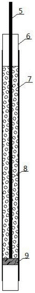
[0025] 15% Cu-CMS is used as the catalyst filling layer 8 . A quartz tube with a diameter of 10mm and a length of 25cm is used as the quartz tube reactor 6, a 3mm copper rod is used as the high voltage electrode 5, and an aluminum foil is used as the ground electrode 7. Take an appropriate amount of 15% Cu-CMS and place it in the reaction system, the flow rate is 300ml / min containing 0.05% NO, 2.8% O 2 , N 2 The mixed gas used as the balance gas is passed into the reaction device, and the ventilation is stopped after 20 minutes of adsorption, and the low-temperature plasma cooperative decomposition reaction is carried out. The plasma output voltage is 7.8KV, the frequency is 8.9KHz, and the discharge time is 10 minutes. Stop. Then repeat the above operation 4 times, single NO x The removal rate was 95%.

Embodiment 2

[0027] A copper-modified activated carbon is used as the catalyst packing layer 8 . A quartz tube with a diameter of 50mm and a length of 30cm is used as the quartz tube reactor 6, an 8mm copper tube is used as the high voltage electrode 5, and copper foil is used as the ground electrode 7. Take an appropriate amount of 10% Cu-AC and place it in the reaction system, pass the mixed gas with a flow rate of 3000ml / min containing 0.05% NO, and air as the balance gas into the reaction device, stop the ventilation after 30 minutes of adsorption, and carry out the low-temperature plasma cooperative decomposition reaction. The plasma output voltage is 7.8KV, the frequency is 8.9KHz, and the discharge time stops after 20min. Then repeat the above operation 3 times, single NO x The removal rate was 95%.


PUM


Abstract

The invention provides a matrix type dielectric barrier plasma synergistic adsorption / catalytic decomposition denitration device, and belongs to the technical field of gas boiler denitration. The device comprises two groups of monomer dielectric barrier discharge plasma synergistic catalyst adsorption / decomposition denitration reactors, one group of plasma generation devices and one set of gas distribution system, wherein the plasma generation devices are positioned between the two groups of the monomer dielectric barrier plasma synergistic catalyst adsorption / decomposition denitration reactors; and by regulating an air inlet three-way valve and an air outlet three-way valve arranged on the device, NOx produced by a gas boiler firstly directly enters one group of the monomer dielectric barrier plasma synergistic catalyst adsorption / decomposition denitration reactors and is adsorbed by using a catalyst filling layer, and the other group of the monomer dielectric barrier plasma synergistic catalyst adsorption / decomposition denitration reactors are communicated with a plasma power supply to perform a process of decomposing NOx by virtue of a plasma synergistic catalyst so as to achieve denitration. The device provided by the invention is simple in structure, low in cost and feasible to operate.

Description

technical field [0001] The invention relates to the technical field of gas boiler denitrification, in particular to a matrix dielectric barrier plasma cooperative adsorption / catalytic decomposition denitrification device. Background technique [0002] With the continuous advancement of China's "coal-to-gas" project and the development of urban social economy, urban central heating gas-fired boilers will become the main equipment for urban heating in winter, and the nitrogen oxides (NO x ) emissions will also increase further. During the "12th Five-Year Plan" period, the NO x Total control index, and for NO x Emission standards are also gradually increasing. Therefore, for the NO of urban central heating boilers x Emissions requirements are also getting stricter. [0003] At present, the commonly used commercial denitrification method is selective catalytic reduction (SCR) technology, which reduces nitrogen oxides by adding a reducing agent such as liquid ammonia to flue...

Claims


Application Information

Patent Timeline
Patent Type & Authority Applications(China)
IPC IPC(8): B01D53/86B01D53/56
Inventor 唐晓龙李东易红宏马玎高凤雨
Owner UNIV OF SCI & TECH BEIJING
Why Eureka
Try Eureka