Residual oil hydrogenation method

A technology for hydrogenation of residual oil and hydrogenation catalyst, which is applied in chemical instruments and methods, treatment with moving solid particles, chemical/physical processes, etc. Easy operation, flexible operation and good product quality

Active Publication Date: 2015-04-29
CHINA PETROLEUM & CHEM CORP +1
View PDF6 Cites 8 Cited by
  • Summary
  • Abstract
  • Description
  • Claims
  • Application Information

AI Technical Summary

Problems solved by technology

Therefore, the existing fluidized bed hydrogenation process has the following disadvantages: (1) The process operation is complicated, requiring the use of complex material level monitors and circulating oil pumps; The bottom of the reactor subsides, causing the unit to be shut down
(2) The amount of catalyst storage in the reactor is low, and the utilization rate of the reactor space is low
(3) The energy consumption is large, and the fluidization of the solid catalyst is realized by injecting a large amount of circulating oil into the circul

Method used


Image

  • Residual oil hydrogenation method
  • Residual oil hydrogenation method
  • Residual oil hydrogenation method

Examples


Embodiment 1

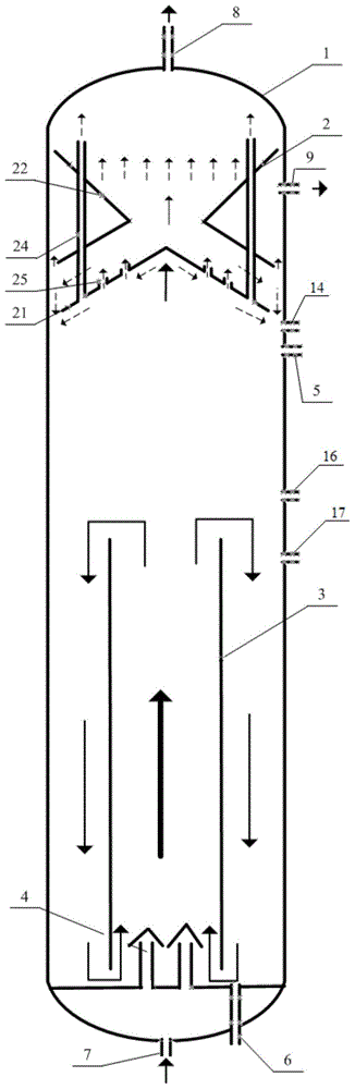
[0092] The specific dimensions of the ebullated bed reactor used in this example are shown in Table 1 below.

[0093] Table 1

[0094] code name

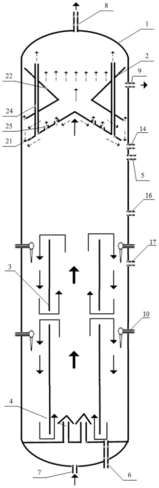
[0095] The above-mentioned ebullated bed reactor was used to carry out the cold model experiment, wherein the solid-phase catalyst added through the catalyst inlet 5 was a spherical catalyst with a particle size of 0.2 mm, and the solid-phase catalyst added through the catalyst inlet 17 was a spherical catalyst with a particle size of 0.3 mm , the colors of the two catalysts are different to facilitate experimental observation. The total catalyst storage is 60% of the effective volume of the reactor. The liquid phase uses straight-run kerosene, and the volume space velocity is 0.25-3.0h -1 . Nitrogen is used in the gas phase, and the gas-oil volume ratio is 20-150. Eight gas nozzles 10 are provided, and the gas volume injected into the gas nozzles accounts for 15% of the total gas volume. The experimental results in t...

Embodiment 2

[0097] The specific dimensions of the ebullated bed reactor used in this example are shown in Table 2 below.

[0098] Table 2

[0099] code name

value

code name

value

d 1 / mm

300

h 1 / mm

3000

d 2 / mm

240

h 2 / mm

1500

d 3 / mm

280

h 3 / mm

900

d 4 / mm

260

α / °

60

d 5 / mm

150

β / °

60

d 6 / mm

285

ω / °

60

d 7 / mm

170

φ / °

60

d 8 / mm

285

The total opening area of ​​the gas separation tube / mm 2

8000

d 9 / mm

160

The total opening area of ​​the through hole / mm 2

15000

d 10 / mm

290

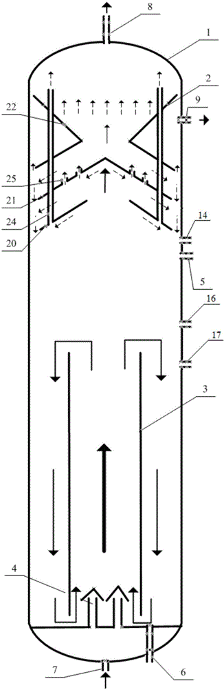
[0100] The above-mentioned ebullated bed reactor was used to carry out the cold model experiment, wherein the solid-phase catalyst added through the catalyst inlet 5 was a spherical catalyst with a particle size of 0.4 mm, and the solid-phase catalyst added through ...

Embodiment 3-5

[0103]Embodiments 3 and 4 adopt the medium-sized thermal reactor made according to the ratio of embodiment 1, and embodiment 5 adopts the medium-sized thermal reactor made according to the ratio of embodiment 2, wherein, the solid-phase catalyst added through the catalyst inlet 5 and The physical and chemical properties of the solid-phase catalyst added through the catalyst inlet 17 are as shown in table 3, and two kinds of solid-phase catalyst loadings are 55% of the effective volume of the reactor, and the volume ratio of the consumption of two kinds of solid-phase catalysts is about 1: 1. The properties of residual oil raw materials are shown in Table 4. Table 5 shows the distillate oil carrying the suspended bed hydrogenation catalyst injected through the catalyst inlet 14 . The amount of gas injected through the nozzle 10 accounts for 20% by volume of the total gas amount. The reaction conditions and test results in the reactor are shown in Table 6.

[0104] table 3

...


PUM


Abstract

The invention relates to a residual oil hydrogenation method. The method is carried out in a fluidized bed reactor; a three-phase separation region, a fluidizing region and a circulation region are arranged in the fluidized bed reactor in sequence from top to bottom. The residual oil hydrogenation method comprises the steps: injecting a first fluidized bed hydrogenation catalyst from the upper part of the circulation region, and injecting a second fluidized bed hydrogenation catalyst and a suspended bed hydrogenation catalyst from the upper part of the fluidizing region to enable the residual oil and hydrogen to be subjected to the hydrogenation reaction in the fluidized bed reactor, wherein the particle size of the first fluidized bed hydrogenation catalyst is 0.05-0.8mm greater than that of the second fluidized bed hydrogenation catalyst; according to corresponding oxide, the content of the active metal components in the first fluidized bed hydrogenation catalyst is10-80 percent lower than that of the active metal components in the second fluidized bed hydrogenation catalyst. According to the residual oil hydrogenation method disclosed by the invention, better reaction effect can be achieved.

Description

technical field [0001] The invention relates to a method for hydrogenation of residue oil, in particular to a method for hydrogenation treatment of residue oil by using an inner circulation fluidized bed reactor, and the method is particularly suitable for processing low-quality residue oil. Background technique [0002] The heavy and inferior crude oil in the world is becoming more and more serious and the market demand for light oil products continues to grow. Therefore, as an effective means of upgrading and lightening residual oil, hydrogenation of residual oil has become one of the development priorities of the oil refining industry. At present, the most commonly used residual oil hydrogenation technology in industry includes fixed bed technology and ebullated bed technology, among which the ebullated bed hydrogenation process has the following advantages: it can process heavy and inferior raw materials with high metal content and high carbon residue value; the reactor t...

Claims


Application Information

Patent Timeline
IPC IPC(8): C10G49/16B01J8/22
CPCB01J8/22C10G49/16
Inventor 邓中活戴立顺牛传峰刘涛邵志才董凯施瑢杨清河
Owner CHINA PETROLEUM & CHEM CORP
Why Eureka
Try Eureka