Method for preparing thermoelectric device and thermoelectric device

A technology of thermoelectric components and components, which is applied in the manufacture/processing of thermoelectric devices, and the material of the junction lead wires of thermoelectric devices, etc.

Active Publication Date: 2015-05-20
SHANGHAI INST OF CERAMIC CHEM & TECH CHINESE ACAD OF SCI +1
View PDF8 Cites 8 Cited by
  • Summary
  • Abstract
  • Description
  • Claims
  • Application Information

AI Technical Summary

Problems solved by technology

[0006] However, for the preparation of special-shaped thermoelectric elements such as hexagons and polygons (the elements include intermediate layers and electrodes), this field has not yet developed a simple and controllable process, and the prepared special-shaped elements have precise dimensions and good surface quality.

Method used


Image

  • Method for preparing thermoelectric device and thermoelectric device
  • Method for preparing thermoelectric device and thermoelectric device
  • Method for preparing thermoelectric device and thermoelectric device

Examples


Embodiment 1

[0099] The hollow structural block was prepared by spark plasma sintering (SPS) according to the following steps:

[0100] The skutterudite material CeFe was prepared by melting and heat treatment 4 Sb 12 . Put 20g of powder into a specially designed graphite mold with a hollow structure. Then, the powder is sintered into a block by SPS process, the heating rate is 40K / min, the sintering temperature is 843K, the holding time is 30min, and the sintering pressure is 60MPa. After cooling in the furnace, the sample with a hollow structure is taken out of the mold, and then, the sample is refined by wire cutting to obtain a sample of predetermined size. Finally, wire cutting or laser cutting is used to cut the block of the hollow structure into thin slices of specified thickness.

Embodiment 2

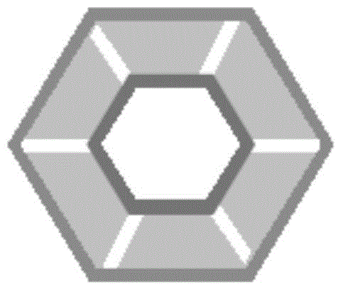
[0102] According to the following steps, the hexagonal hollow block is prepared by spark plasma sintering method:

[0103] The composition is ZrNiSn prepared by solid state reaction or arc melting heat treatment. 0.99 Sb 0.01 s material. 20 g of powdered material was put into a graphite mold with a hexagonal structure. Then, the powder is sintered into a block using the SPS process. The heating rate is 30K / min, the sintering temperature is 923K, the holding time is 30min, and the sintering pressure is 50MPa. After the furnace cools, the samples are removed from the molds. Use a drilling machine to drill a 1mm hole axially in the center of the sample, and then use wire cutting to form a hexagonal cavity in the center of the sample. Finally, the hexagonal hollow block is cut into slices of predetermined size and thickness.

Embodiment 3

[0105] According to the following steps, the hexagonal hollow block is prepared by hot pressing sintering and assembly method:

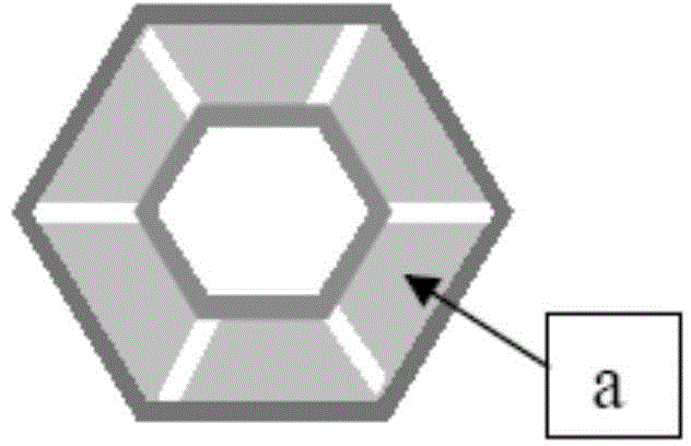
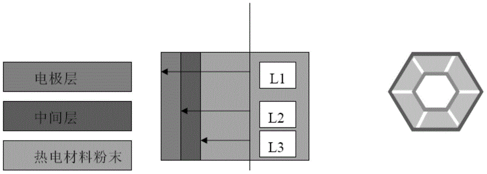
[0106] The skutterudite material Yb was prepared by melting and heat treatment 0.3 CO 4 Sb 12 . Put the electrode sheet, the middle layer sheet and 20g of skutterudite powder into a square graphite mold. Then, the powder is sintered into a block by hot pressing, the heating rate is 40K / min, the sintering temperature is 893K, the holding time is 60min, and the sintering pressure is 30MPa. After cooling in the furnace, the square samples were removed from the molds. The sample is then machined using wire EDM, cut and finished into preset components (see figure 1 In a), the bottom of the trapezoid of the finishing part is the electrode layer (hot end). The cold terminal electrode is formed on the upper bottom of the trapezoidal part by means of electroplating. Finally, assemble the six parts into a complete thermoelectric element with a hexagonal...


PUM


Abstract

The invention relates to a method for preparing a thermoelectric device and a thermoelectric device, and provides a method for preparing a thermoelectric device. The method comprises the following steps: (a) providing a large number of thermoelectric material sheets or thermoelectric component sheets, wherein each sheet has at least one predetermined shape; (b) arranging the thermoelectric material sheets or thermoelectric component sheets into a predetermined combination, and connecting the thermoelectric material sheets or thermoelectric component sheets to form a thermoelectric material section or thermoelectric component section; (c) repeating step (b) to produce a large number of sections; and (d) connecting the large number of sections to produce a predetermined configuration for thermoelectric devices. The invention further provides a thermoelectric device.

Description

technical field [0001] The invention belongs to the field of thermoelectric materials and devices, and relates to a method for directly preparing hollow thermoelectric samples with simple process and easy control. More specifically, it relates to a method for preparing thermoelectric components and thermoelectric components. Background technique [0002] Thermoelectric technology is capable of converting heat into electricity and vice versa. This environmentally friendly technology has many advantages over other technologies, such as no mechanical parts and thus no noise in use, and less maintenance. Unlike previous applications such as military, medical, and space, thermoelectric technology applications have recently shifted to generating electricity from automotive and industrial waste heat. Many industrial and transportation processes are accompanied by waste heat due to the combustion of fossil fuels, whose rising prices and damaging effects on the environment have fue...

Claims


Application Information

Patent Timeline
Patent Type & Authority Applications(China)
IPC IPC(8): H01L35/34H01L35/16
Inventor 黄向阳陈立东李小亚唐云山夏绪贵
Owner SHANGHAI INST OF CERAMIC CHEM & TECH CHINESE ACAD OF SCI
Why Eureka
Try Eureka