Container corrugated plate welding robot and visual servo control system thereof

A visual servo and control system technology, applied in the direction of digital control, welding equipment, welding equipment, etc., can solve the problems of high welding technology, affecting welding accuracy, easy water leakage, light leakage, etc., and achieve high intelligence, good welding quality, The effect of high welding efficiency

Active Publication Date: 2015-07-08
SHENZHEN CIMC SECURITY & SMART TECH
View PDF4 Cites 25 Cited by
  • Summary
  • Abstract
  • Description
  • Claims
  • Application Information

AI Technical Summary

Problems solved by technology

Since the container corrugated plate starts from blanking and stamping, through the butt welding between the corrugated plates, and the fillet welding between the bottom plate and the corrugated plate, there are certain errors in each link, which makes the assembly gap track have certain irregular fluctuations, and the gap The size is also changing. On the other hand, the thermal influence during the welding process causes a certain deformation in the assembly gap to be welded, which makes the assembly gap inconsistent. Therefore, real-time monitoring and tracking of the assembly weld seam is required.
The corrugated plate used in the container is easy to be welded and broken during welding, so high welding technology is required. When manual welding is performed, the toe needs to be moved after the weld is 500mm long, and the welded joint will be formed when the welding is continued, and the welded joint is prone to water leakage. , light leakage, weld bead joints protruding from the outer edge of the upper side beam, and manu

Method used


Image

  • Container corrugated plate welding robot and visual servo control system thereof
  • Container corrugated plate welding robot and visual servo control system thereof
  • Container corrugated plate welding robot and visual servo control system thereof

Examples


Embodiment Construction

[0019] In order to further illustrate the principle and structure of the present invention, preferred embodiments of the present invention will now be described in detail with reference to the accompanying drawings.

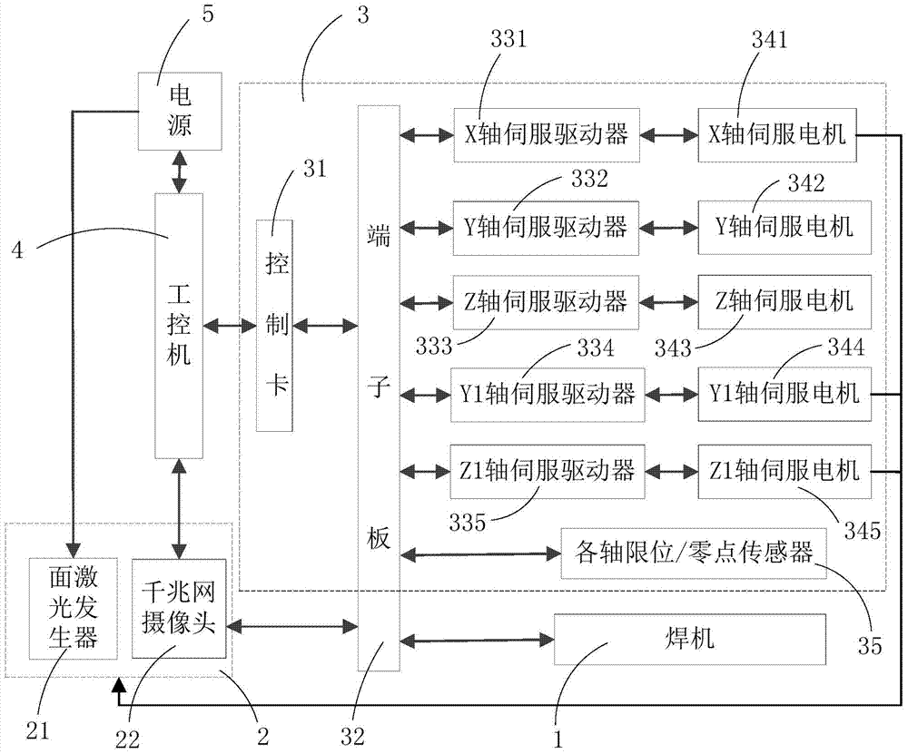
[0020] refer to figure 1 , the present invention provides a visual servo control system for corrugated plate welding of containers, the visual servo control system is mainly used for weld recognition and tracking control of corrugated plate welding, roughly composed of welding machine 1, visual sampling mechanism 2, motion The control mechanism 3, the industrial computer 4 and the power supply 5 are composed of five parts.

[0021] The welding machine 1 includes a welding power supply for providing welding current and voltage to the welding torch, a wire feeder for sending the welding wire to the weld seam and a shielding gas source for providing welding shielding gas; The machine 1 works with the set welding parameters to ensure the welding operation of the wel...


PUM


Abstract

The invention discloses a container corrugated plate welding robot and a visual servo control system thereof. The visual servo control system comprises an industrial personal computer, a visual sampling mechanism and a motion control mechanism, wherein the visual sampling mechanism comprises a surface laser generator, a network camera, and an optical filter arranged in front of the network camera; the network camera is connected with the industrial personnel computer in a network communication manner; the motion control mechanism comprises a control card connected with the industrial personnel computer, five servo drivers in two-way communication connection with the control card, five servo motors correspondingly driven by the five servo drivers, and limit/zero-point sensors connected with the control card; the five servo motors respectively and correspondingly drive the motions of a welding gun and the visual sampling mechanism; the limit/zero-point sensors are respectively arranged in five motion directions controlled by the five servo motors; and the control card is further connection with the network camera. The visual servo control system controls based on visual servo, can accurately perform the tracking welding of welding lines, and is high in welding efficiency and excellent in welding quality.

Description

technical field [0001] The invention relates to the field of welding control, in particular to a visual servo control system for welding container corrugated plates and a container corrugated plate welding robot using the visual servo control system. Background technique [0002] Containers are modular transportation equipment that have appeared in recent years. Since their appearance, they have rapidly occupied the freight market. The standard dry cargo containers produced in China account for more than 95% of the world's output, and have always maintained the number one position in the world. Containers are used all over the world, and their size and shape are standard. Due to the large demand, their production is generally a mass industrial production line, and the various processes are connected with each other. The welding of the bottom of the box is the welding of the side wall corrugated plate. Since the container corrugated plate starts from blanking and stamping, t...

Claims


Application Information

Patent Timeline
IPC IPC(8): B23K9/12B23K9/127G05B19/18
CPCB23K9/1274B23K37/0252B23K2101/18
Inventor 周受钦吕洁印常勇谢恒星肖海兵曹广忠
Owner SHENZHEN CIMC SECURITY & SMART TECH
Why Eureka
Try Eureka