

transfer film
A technology of transfer film and substrate film, applied in decorative arts, electronic equipment, applications, etc., can solve the problems of mold release layer damage, poor transfer, poor appearance, etc., to achieve less environmental load, excellent mold release, Excellent hard coat function and design effect
- Summary
- Abstract
- Description
- Claims
- Application Information
AI Technical Summary
Problems solved by technology
Method used
Image


Examples
Embodiment
[0076] The present invention will be described in detail below using examples.
[0077]
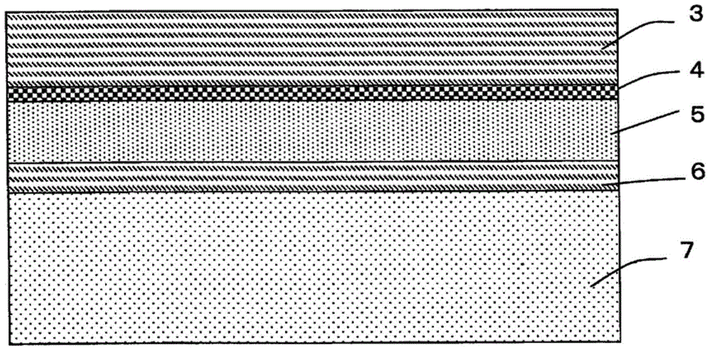
[0078] A biaxially stretched polyester film (manufactured by Mitsubishi Plastics Corporation: G440E50) with a thickness of 50 μm was used as the base film 1, and the following was applied on one surface by the microgravure method so that the film thickness after drying became 0.2 μm. The composition of the coating liquid for the release layer is dried. Thereafter, aging was performed at 50° C. for 5 days to form the release layer 2 .
[0079] (Composition of Coating Liquid for Release Layer)
[0080] Acrylic polyol resin (LC#6560 manufactured by Toei Chemical Co., Ltd.): 100 parts by weight
[0081] Nitrocellulose (H1 / 4): 10 parts by weight
[0082] Acrylic resin: 5 parts by weight
[0083] (It is a copolymer of 6-hydroxyhexyl acrylate and stearyl methacrylate, and has a hydroxyl group and a long-chain alkyl group (18 carbons))
[0084] Isocyanate compound: 20 parts by weight
[0...
Embodiment 2
[0095] The mold release layer 2 was formed similarly to Example 1 except having used the coating liquid for mold release layers of the following composition.
[0096] (Composition of Coating Liquid for Release Layer)
[0097] Acrylic polyol resin (LC#6560 manufactured by Toei Chemical Co., Ltd.): 100 parts by weight
[0098] Nitrocellulose (H1 / 4): 10 parts by weight
[0099] Acrylic resin: 5 parts by weight
[0100] (It is a copolymer of 6-hydroxyhexyl acrylate and stearyl methacrylate, and has a hydroxyl group and a long-chain alkyl group (18 carbons))
[0101] Silicone-modified acrylic resin (manufactured by NOF: FS730): 5 parts by weight
[0102] Isocyanate compound: 20 parts by weight
[0103] (CORONATE L manufactured by Japan Polyurethane Co., Ltd.)
[0104] Next, the coating liquid for hard-coat layers of the following composition was apply|coated by the microgravure method so that the film thickness after drying might become 5.0 micrometers, and it dried. In this ...
Embodiment 3
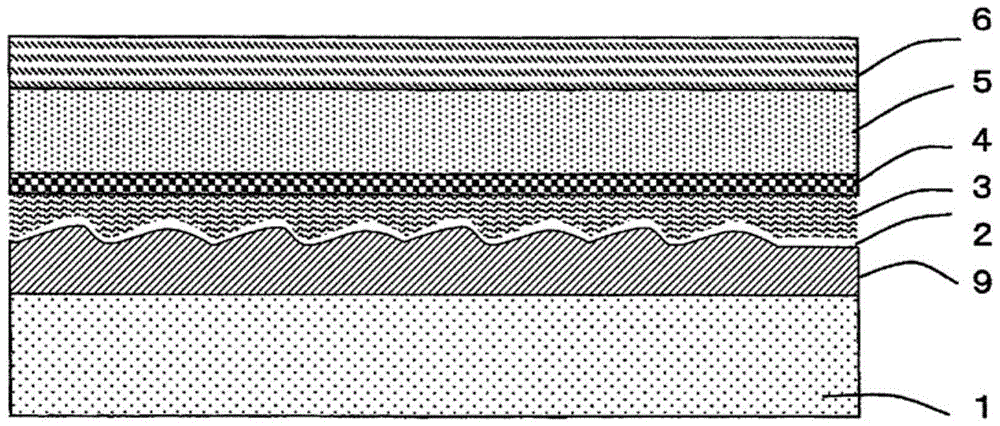
[0113] Using the same substrate film 1 as in Example 1, an anchor layer coating solution having the following composition was applied to one surface by the microgravure method so that the film thickness after drying became 5.0 μm, and dried. In this way, the anchor layer 9 is formed.
[0114] (Composition of Coating Liquid for Anchor Layer)
[0115] Acrylic polyol resin: 100 parts by weight
[0116] (Manufactured by Toei Chemical Co., Ltd.: LC#6560)
[0117] Silica filler (manufactured by Evonik Degussa: particle size: 6 μm): 5 parts by weight
[0118] Polyacrylonitrile filler (manufactured by Toyobo Co., Ltd.: particle size: 7 μm): 5 parts by weight
[0119] Isocyanate compound: 10 parts by weight
[0120] (Japan Polyurethane Co., Ltd.: CORONATE HL)
[0121] Next, a release layer coating liquid having the following composition was applied on the anchor layer 9 by the microgravure method so that the film thickness after drying became 1.0 μm, and dried. In this way, the r...
PUM
| Property | Measurement | Unit |
|---|---|---|
| thickness | aaaaa | aaaaa |
| thickness | aaaaa | aaaaa |
| thickness | aaaaa | aaaaa |
Abstract
Description
Claims
Application Information