
High sulfur crude oil oil-gas recovery technology and oil-gas recovery system

An oil and gas recovery system and high-sulfur crude oil technology, which is applied in the petroleum industry and the recovery of liquid hydrocarbon mixtures, etc., can solve the problems of difficult to reach the standard of sulfur content in oil and gas, low penetration of sulfur in the desulfurization tower, poor desulfurization effect, etc., and achieve low desulfurization cost , The effect of reducing the amount of engineering and the amount of loading

Active Publication Date: 2015-08-12
上海森鑫新能源科技有限公司
View PDF6 Cites 1 Cited by
  • Summary
  • Abstract
  • Description
  • Claims
  • Application Information

AI Technical Summary

Problems solved by technology

[0022] The purpose of the present invention is to provide a high-sulfur crude oil gas recovery process to solve the problem of penetrating sulfur in the desulfurization tower due to the high concentration of sulfide entering the desulfurization tower in the existing oil gas recovery process. It is a technical problem that the sulfur content in the desulfurized oil and gas is difficult to meet the standard due to the low capacity and poor desulfurization effect.
[0023] Another object of the present invention is to provide an oil gas recovery system for the above-mentioned high-sulfur crude oil gas recovery process, to solve the problem of high concentration and variety of sulfides entering the desulfurization tower in the existing oil gas recovery process. The composition is relatively complex, which leads to a low penetration sulfur capacity of the desulfurization tower and a poor desulfurization effect, which makes it difficult for the sulfur content in the desulfurized oil and gas to meet the technical problem

Method used


Image

  • High sulfur crude oil oil-gas recovery technology and oil-gas recovery system
  • High sulfur crude oil oil-gas recovery technology and oil-gas recovery system
  • High sulfur crude oil oil-gas recovery technology and oil-gas recovery system

Examples


Embodiment 1

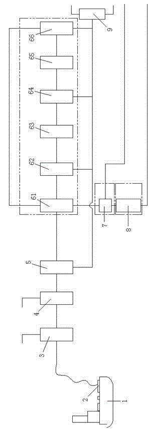
[0080] see figure 1 , an oil and gas recovery system for high-sulfur crude oil and gas recovery process, including a compression device 4, a cooling device (not shown in the figure), a separation device X5, a condensation separation subsystem, an activated carbon adsorption device 7 and a desulfurization device 8, the The compression device 4, the cooling device, the separation device X5, the condensation separation subsystem, the activated carbon adsorption device 7, and the desulfurization device 8 are connected in sequence. The oil and gas recovery system of the present invention condenses most of the sulfur-containing compounds and hydrocarbons into liquids through the condensation and separation subsystem, so that the types and quantities of sulfur-containing compounds entering the desulfurization device are less and the components are relatively simple, which can make the desulfurization device The penetration sulfur capacity is higher, and the desulfurization effect is ...

Embodiment 2

[0088] The difference between this embodiment and Embodiment 1 is that the condensation separation subsystem includes a condenser I and a separation device I, and the oil and gas recovery system also includes a dehydration device I, and the dehydration device I is connected to the gas outlet of the separation device X , the gas outlet of the dehydration device I is connected to the condenser I, the condenser I is connected to the separation device I, and the gas outlet of the separation device I is connected to the activated carbon adsorption device. Other structures and principles of this embodiment are the same as those of Embodiment 1, and will not be repeated here.

[0089] In this embodiment, only one set of condensing devices is provided, the structure is simple, the energy consumption is small, and the cost of oil and gas recovery is lower.

Embodiment 3

[0091] The difference between this embodiment and Embodiment 1 is that the condensation separation subsystem includes condenser III, separation device III, condenser IV and separation device IV, the oil and gas recovery system also includes dehydration device II, and the separation device X The gas outlet of the dehydration device II is connected to the condenser III, the condenser III is connected to the separation device III, the dehydration device II is connected to the gas outlet of the separation device III, and the gas outlet of the dehydration device II is connected to the dehydration device II. The condenser IV is connected, the condenser IV is connected with the separation device IV, and the gas outlet of the separation device IV is connected with the activated carbon adsorption device. Other structures and principles of this embodiment are the same as those of Embodiment 1, and will not be repeated here.

[0092] In this embodiment, two sets of condensing devices are...


PUM


Abstract

The present invention provides a high sulfur crude oil oil-gas recovery technology and oil-gas recovery system. The oil-gas recovery technology includes the following steps: a. high sulfur crude oil oil-gas is compressed, the compressed oil-gas is cooled, then gas and liquid separation is performed, and the separated liquid is collected; b, the separated oil-gas of the step a is condensed, then gas and liquid separation is performed, and the separated liquid is collected; c, the separated oil-gas of the step b is introduced into an activated carbon adsorption device, and is desulfurized, and desorption and collection of hydrocarbons in the activated carbon adsorption device are performed. According to the high sulfur crude oil oil-gas recovery technology, most of sulfides and hydrocarbons are condensed into liquid in the condensation processing process, species and quantity of sulfides entering into a desulfurization tower are less, and the composition is simple, so that breakthrough sulfur capacity of the desulfurization tower is high, the desulfurization effect is better, and when the sulfur content in the desulfurized oil-gas is very easy to meet.

Description

technical field [0001] The invention relates to the technical field of crude oil gas recovery, in particular to a high-sulfur crude oil gas recovery process and an oil gas recovery system. Background technique [0002] Crude oil volatiles are mainly hydrocarbons and sulfides, hydrocarbons include CH 4 、C 2 h 6 、C 3 h 8 etc., are flammable gases; sulfides include H 2 S, carbonyl sulfide, mercaptan, thioether, thiophene, disulfide compound, etc. Arbitrary discharge of crude oil volatiles will not only bring environmental pollution, but also directly endanger the living environment of human beings. Since most light oil products are volatile, flammable and explosive substances, they are easy to gather, form an explosive mixture with air, and then settle in depressions or pipe trenches, which are prone to explosion or fire accidents in case of fire, resulting in loss of life and property. huge loss. Due to the wide range of oil-gas explosion limit and the wide range of oi...

Claims


Application Information

Patent Timeline
Patent Type & Authority Applications(China)
IPC IPC(8): C10G5/06
Inventor 白爽史成
Owner 上海森鑫新能源科技有限公司
Learn More