
Detection method of hot shear cutter material laser shock residual stress thermal relaxation

A technology of residual stress and laser shock, which is applied in the detection and analysis of material processing, and in the field of mechanical manufacturing, can solve the problem of affecting structural fatigue strength, brittle fracture resistance, stress corrosion cracking and high temperature creep cracking, reducing structural stiffness and stability In order to achieve the effect of low cost, easy operation and high detection efficiency

Inactive Publication Date: 2015-08-12
JIANGSU UNIV
View PDF3 Cites 8 Cited by
  • Summary
  • Abstract
  • Description
  • Claims
  • Application Information

AI Technical Summary

Problems solved by technology

The scissor blade in hot shear is to cut and cut the steel material of the primary rolling steel plant at about 800-1000 ℃. In addition to requiring strong impact toughness and high temperature strength, the surface of the cutting edge of the tool also needs to be very strong. Strong hardness, strong wear resistance, thermal stability, and thermal fatigue resistance; residual stress will be generated during the working process, but the existence of thermal relaxation of residual stress will not only reduce the rigidity and stability of the structure but also reduce the stiffness and stability of the structure under temperature and Under the combined action of the medium, it will also seriously affect the fatigue strength of the structure, the ability to resist brittle fracture, the ability to resist stress corrosion cracking and high temperature creep cracking

Method used

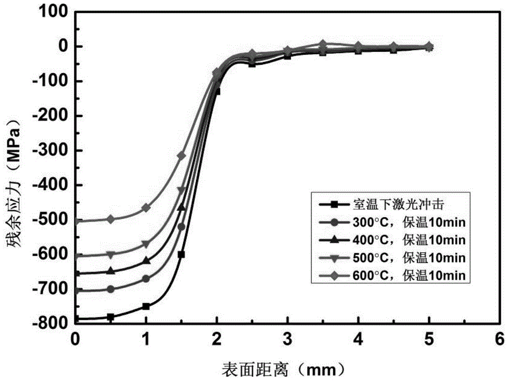
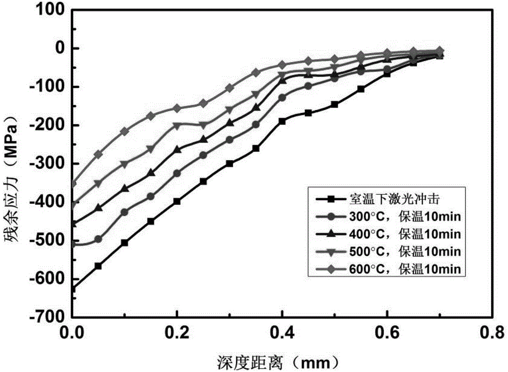
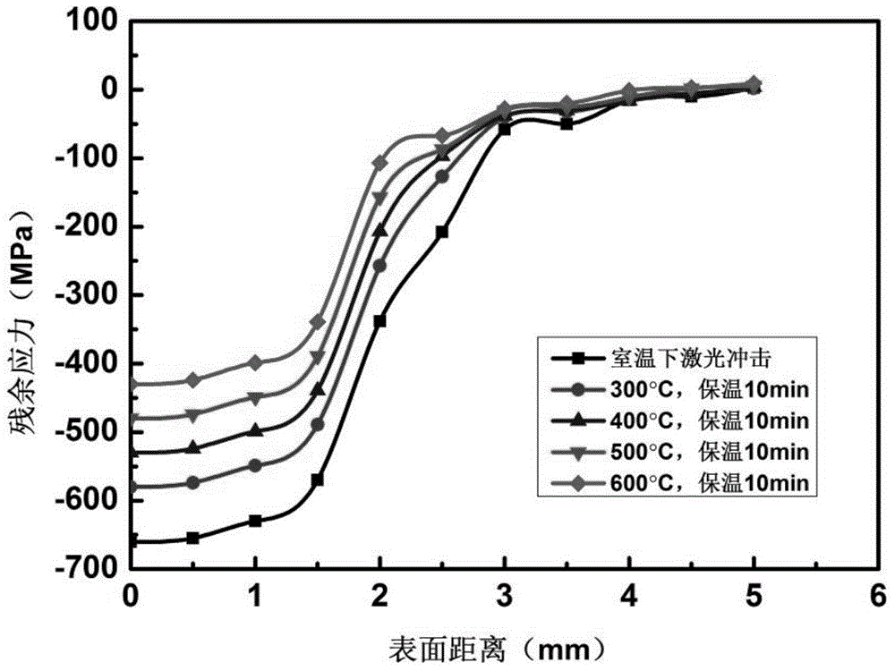

Image

  • Detection method of hot shear cutter material laser shock residual stress thermal relaxation
  • Detection method of hot shear cutter material laser shock residual stress thermal relaxation
  • Detection method of hot shear cutter material laser shock residual stress thermal relaxation

Examples


Embodiment Construction

[0028] The present invention will be further described below in conjunction with the accompanying drawings and specific embodiments, but the protection scope of the present invention is not limited thereto.

[0029] A method for detecting thermal relaxation of thermal scissors material laser shock residual stress, comprising the following steps:

[0030] (1) Establish the finite element model of the hot shear tool material:

[0031] Cut the hot shear tool material 6CrW2Si steel into rectangular pieces with length, width and height of 10cm, 10cm and 5cm respectively, and use the Y axis as the central axis of symmetry in the simulation software ANSYS / LS_DYNA, and the X-Z plane as the laser shock plane Create its geometric model; the element selection is 8-node hexahedral element SOLID164; the mesh division process is to refine the mesh in the area of ​​2 times the length of the spot radius on the three coordinate axes, and use sparse mesh for the rest; select the JC model as the...


PUM

PropertyMeasurementUnit
Radiusaaaaaaaaaa

Abstract

The invention provides a detection method of hot shear cutter material laser shock residual stress thermal relaxation. The detection method comprises following steps: a hot shear cutter material is cut into cuboid small pieces, and the length, width, and height of the cuboid small pieces are measured; a geometric model is constructed in simulation software ANSYS / LS_DYNA, and a finite element model is obtained via unit selection, mapped meshing, constitutive model selection, and boundary condition application; laser parameters are set, simulation of laser shock on the finite element model is carried out in a S-shaped light spot impact trajectory; surface residual stress and depth residual stress of the finite element model are measured after impact; at a same thermal holding time, temperature load of the finite element model is changed, and surface residual stress and depth residual stress of the finite element model are measured, so that residual stress thermal relaxation under different temperature load is obtained. Operation of the detection method is simple and convenient; detection efficiency is high; cost is low; the detection method is friendly to the environment; no pollution is caused; and optimum parameters can be provided for subsequent hot shear cutter impact modification.

Description

technical field [0001] The invention belongs to the technical field of mechanical manufacturing, material processing and processing detection and analysis, and in particular relates to a detection method for thermal relaxation of thermal shear tool material laser shock residual stress. Background technique [0002] In advanced manufacturing technology, laser shock processing technology, as a typical representative of high-energy beam, is a processing method with good prospects. Its principle is to use high-power short-pulse laser to interact with the surface of materials to modify the surface of materials. especially fatigue life. This technology has been widely used in various industries such as mechanical engineering, shipbuilding, aviation, and microelectronics. At present, this technology is mainly used in material modification, metal impact strengthening and forming, and non-destructive testing. [0003] The finite element analysis software ANSYS / LS_DYNA, as a display ...

Claims


Application Information

Patent Timeline
IPC IPC(8): G01N33/20
Inventor 任旭东戴文杰殷文元任乃飞刘小梅谢善忠崔卫东尹小琴张西良王匀王存堂张晓荣谢方伟
Owner JIANGSU UNIV
Learn More