Treatment device equipped with catalyst-supporting honeycomb structure and process for producing same

A technology of honeycomb structure and processing device, which is applied in the direction of catalyst carrier, catalyst activation/preparation, and device for coating liquid on the surface, etc., which can solve the problems of increased pressure loss, etc., and achieve the effect of shortening the manufacturing process and low manufacturing cost

Active Publication Date: 2015-09-16
HITACHI ZOSEN CORP
View PDF7 Cites 2 Cited by
  • Summary
  • Abstract
  • Description
  • Claims
  • Application Information

AI Technical Summary

Problems solved by technology

In addition, the pressure loss will also increase

Method used


Image

  • Treatment device equipped with catalyst-supporting honeycomb structure and process for producing same
  • Treatment device equipped with catalyst-supporting honeycomb structure and process for producing same
  • Treatment device equipped with catalyst-supporting honeycomb structure and process for producing same

Examples


Embodiment 1

[0117] By the method of the present invention, a denitration catalyst-supporting honeycomb treatment device was produced as follows.

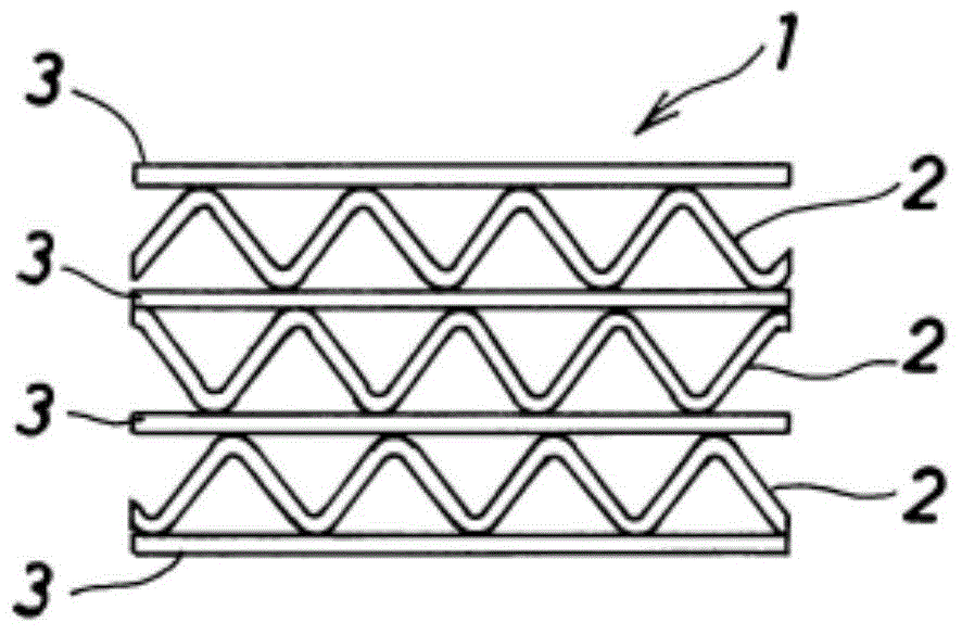
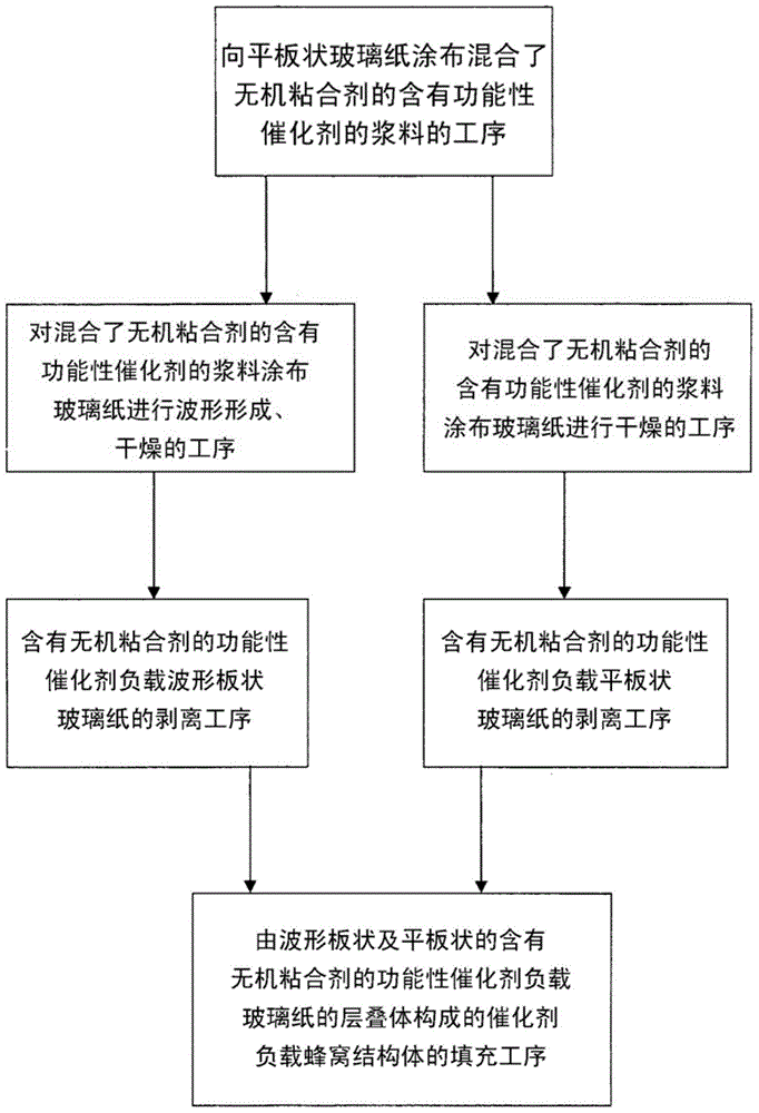
[0118] Implemented in sequence image 3 The manufacturing method of the processing apparatus provided with the catalyst supporting honeycomb structure of this invention is shown.

[0119] First, as a commercially available cellophane, at a fiber content of 100g / m 2 , On a flat cellophane (20×30cm) with a content of 10% by weight of an acrylic resin organic binder, at 1333g / m 2 The coating amount of the functional catalyst-containing slurry mixed with an inorganic binder is coated.

[0120] As the functional catalyst, a denitration catalyst is used. That is, ammonium metavanadate powder is added to the slurry in which titanium dioxide fine particles are suspended in silica sol, and the whole is stirred to adsorb ammonium metavanadate on titanium dioxide. Silica sol was used as an inorganic binder, and the content of silica sol in the denitra...

Embodiment 2

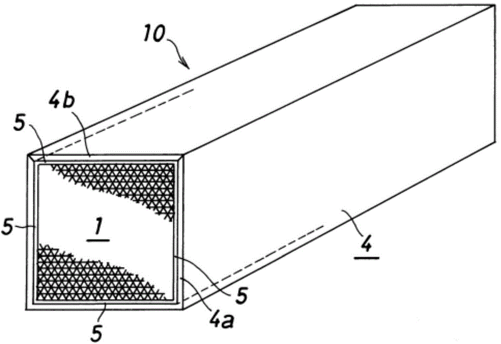
[0130] Similar to the case of the above-mentioned Example 1, the processing device (10) equipped with the denitration catalyst-supported honeycomb structure (1) was manufactured by the method of the present invention, but the difference from the case of the above-mentioned Example 1 is that each mold Heated to a surface temperature of 250°C for use. The processing apparatus (10) provided with the denitration catalyst supporting honeycomb structure (1) of this invention was manufactured similarly to the case of the said Example 1 except the surface temperature of this mold|die.

Embodiment 3

[0132] Similar to the case of the above-mentioned Example 1, the processing device (10) equipped with the denitration catalyst-supported honeycomb structure (1) was manufactured by the method of the present invention, but the difference from the case of the above-mentioned Example 1 is that each mold Heated to a surface temperature of 200°C for use. Except for the surface temperature of the mold, a processing device ( 10 ) including a catalyst-supporting honeycomb structure ( 1 ) of the present invention was produced in the same manner as in Example 1 above.


PUM


Abstract

[Problem] To provide a treatment device equipped with a catalyst-supporting honeycomb structure, the device being for use in, for example, discharge gas purification or hydrogen production by ammonia decomposition, and a process for producing the treatment device. The catalyst-supporting honeycomb structure is produced by forming corrugated glass paper on which an inorganic-binder-containing functional catalyst is supported, without the necessity of removing the organic binder intrinsically contained in the glass paper, and by using the corrugated glass paper in combination with flat glass paper on which an inorganic-binder-containing functional catalyst is supported. Due to this, not only steps for producing a treatment device equipped with a catalyst-supporting honeycomb structure are greatly shortened, but also the production cost is lowered. [Solution] The treatment device equipped with a catalyst-supporting honeycomb structure comprises the catalyst-supporting honeycomb structure (1) and a casing (4) in which the catalyst-supporting honeycomb structure (1) has been packed, the catalyst-supporting honeycomb structure (1) having been formed by alternately superposing corrugated glass paper that has an inorganic-binder-containing functional catalyst supported thereon and flat glass paper that has, supported thereon, the same inorganic-binder-containing functional catalyst.

Description

technical field [0001] The present invention relates to a processing device equipped with a catalyst-supporting honeycomb structure and a manufacturing method thereof, which are used, for example, for purification of exhaust gas or production of hydrogen by decomposition of ammonia. Background technique [0002] Conventionally, it has been difficult to use commercially available cellophane as a base material of a honeycomb structure (flat plate+corrugated plate) used in a treatment device including a catalyst-carrying honeycomb structure for exhaust gas purification treatment or the like. [0003] For example, if a commercially available cellophane is to be shaped into a corrugated plate using a corrugator (wave forming machine), the organic binder contained in the cellophane has a large repulsive force, and even if the flat cellophane is bent under pressure, it will return to its original shape. to the previous state. In addition, if too much pressure is applied, the cello...

Claims


Application Information

Patent Timeline
Patent Type & Authority Applications(China)
IPC IPC(8): B01J35/04B01D53/86B01J23/22B05D7/00B05D7/24
CPCB01D53/885F01N2310/02F01N3/2066B01D46/2418F01N2330/101B01J23/22B01J35/04B01J37/0234C04B38/0006C04B2111/0081Y10T29/49346Y02T10/12C04B35/46C04B35/6316C04B38/0083F01N3/28
Inventor 山本诚吾日数谷进日野尚荣坪史弥小玉哲男平岩俊介幸丸良一
Owner HITACHI ZOSEN CORP
Why Eureka
Try Eureka