Continuous detector for multi-wavelength excited fluorescence labeling immune test strips

A technology of fluorescent labeling and exciting fluorescence, applied in the field of fluorescently labeling immune sample detection, can solve the problems of poor laser light intensity and thermal stability, complex manufacturing process, limited use of instruments, etc., to reduce the influence of background light, simple design structure, saving energy The effect of detection time

Inactive Publication Date: 2015-09-23
NORTHEAST DIANLI UNIVERSITY
View PDF6 Cites 18 Cited by
  • Summary
  • Abstract
  • Description
  • Claims
  • Application Information

AI Technical Summary

Problems solved by technology

Due to the relatively poor thermal stability of the laser light intensity, it is easy to cause drift errors. The cost of a laser with stable performance is high, and the manufacturing process is relatively complicated, so it is not easy to realize
Using photodiode and photomultiplier tube to detect the fluorescence emitted by the object after optical condensing will be interfered by other background light, and the degree of influence is relatively large
When the photomultiplier tube is used as a fluorescence detection component, its photon conversion efficiency is only 5-10% when the fluorescence wavelength of the immunoassay strip is about 600nm, so it is not suitable for detecting low-concentration samples
Moreover, the existing fluorescent test paper detection instrument can only detect one test paper strip at a time, and the detection wavelength is fixed, so the use of the instrument is limited.
The time required for different detected objects is different, and it is difficult for the operator to grasp the best detection time, which affects the detection accuracy and wastes a lot of time and financial resources

Method used


Image

  • Continuous detector for multi-wavelength excited fluorescence labeling immune test strips
  • Continuous detector for multi-wavelength excited fluorescence labeling immune test strips
  • Continuous detector for multi-wavelength excited fluorescence labeling immune test strips

Examples


Embodiment 1

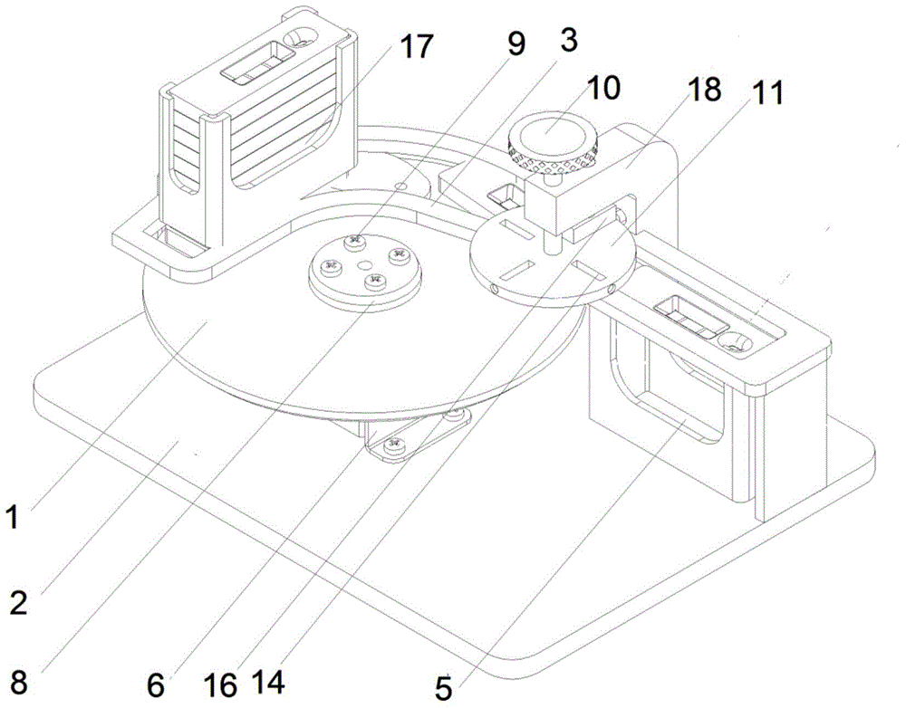
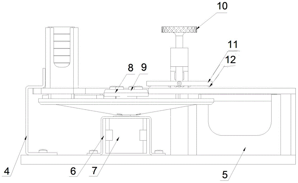
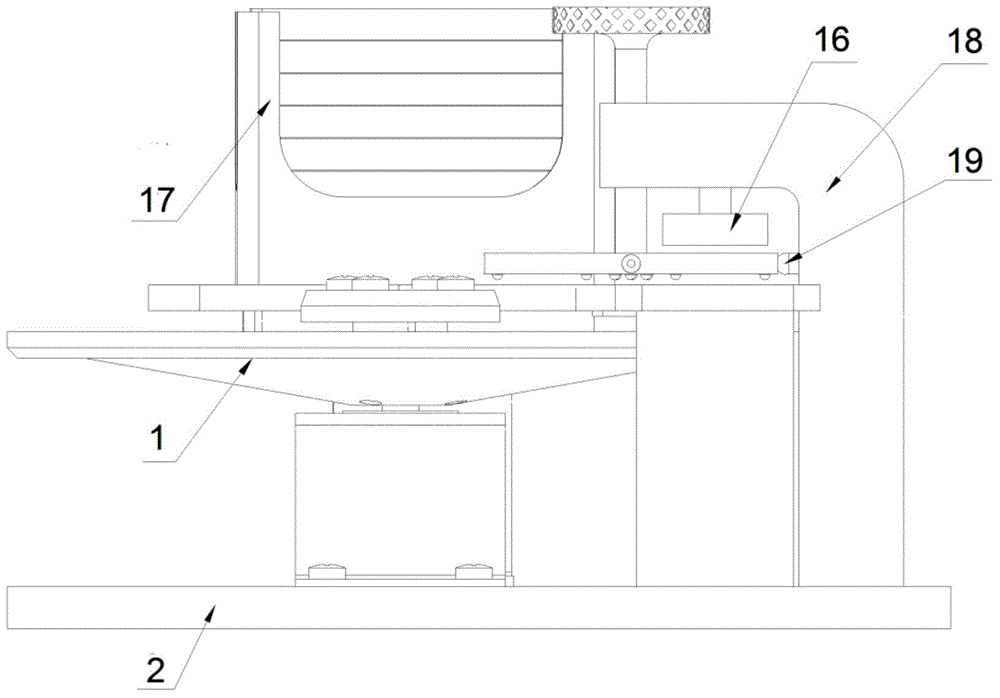
[0030] Example 1 see Figure 1~5 The overall structure of the continuous multi-wavelength excitation fluorescence-labeled immunological test strip detector of the present invention is illustrated.

[0031] The structure of the invention has a mechanical transmission system, an optical system and an image acquisition system.

[0032] The mechanical transmission system consists of a slideway turntable 1, a test strip placement slot 17, a test strip slideway 3, a support frame 4, a test strip collection tank 5, a motor support 6, a stepping motor 7, a pressure pad 8, The tight shaft sleeve 9 is composed of; the stepper motor 7 is located in the motor bracket 6 and fixed on the seat plate 2, which is connected to the slideway turntable 1 and fixed by the pressure pad 8 and the tight shaft sleeve 9, that is, the main shaft of the stepper motor 7 Connected with the rotating shaft of the slideway turntable 1, the stepper motor 7 can drive the slideway turntable 1 to rotate; the top ...

Embodiment 2

[0039] Embodiment 2 Control and switching of LED excitation light source 12

[0040] In the present invention, since a group of LED excitation light sources 12 are installed at both ends of each rectangular hole, four groups of LED excitation light sources 12 can switch excitation lights of four wavelengths, and the intensity of light can be adjusted by changing the voltage applied to the LED excitation light sources 12. Adjustment, that is, the control of light intensity is realized by controlling the actual current of the LED light source 12; it is also possible to use 6 LED excitation light sources 12 as a group, and install 3 LED excitation light sources 12 at both ends of each rectangular hole, which can be selectively Turn off one pair or two pairs of LED excitation light sources 12 to realize effective control of light intensity.

[0041] The excitation light source and switching structure are: LED excitation light source 12 is composed of 24 LEDs, and every 6 LEDs have...

Embodiment 3

[0042] Embodiment 3 A structure to realize stray light filtering and fluorescence focusing.

[0043] After the light emitted by the LED excitation light source 12 is irradiated on the fluorescently labeled immune test strip to be detected, there are three ways to filter stray light for the excited fluorescence: the fluorescence passes through the filter 14 and then passes through the slit 13; the fluorescence passes through the slit 13 After passing through the optical filter 14; the fluorescence passes through the optical filter 14, then passes through the slit 13 and then is filtered by the second optical filter 14; wherein the width of the slit 13 is consistent with the size of the detection zone on the test strip. The third method for filtering stray light requires two optical filters 14 installed on both sides of the slit 13 respectively.

[0044] It can be seen that the positional relationship between the slit 13 and the filter 14 can be interchanged, which one is on the...


PUM


Abstract

The invention provides a continuous detector for multi-wavelength excited fluorescence labeling immune test strips and belongs to the technical field of fluorescence labeling immune sample detection. The continuous detector consists of a mechanical transmission system, an optical system and an image acquisition system. Fluorescence labeling immune test strips in a test strip placing groove (17) fall into a test strip chute (3) and are pushed to a light source turntable (18) by a rotating chute disk (1) to be detected. An LED excitation light source (12), a slit (13) and a light filter (14) are mounted at the rectangular hole in the light source turntable (18), and fluorescent light is subjected to stray light filtration, focused by a focusing lens (15), then received by a CCD linear array sensor (16) and finally treated by the image acquisition system to realize detection of the immune test strips. The continuous detector has the advantages that continuous on-line detection and different-wavelength fluorescence test strip detection are achieved, light intensity control is realized to lower the test strip preparation demands, noise is eliminated effectively, the wave crests of the detected fluorescent light are accurately read, and the detection precision is improved.

Description

technical field [0001] The invention belongs to the technical field of fluorescently labeled immune sample detection, and is an instrument for continuously detecting laser-induced fluorescently labeled immune test strips. The device can perform continuous and rapid detection and result judgment on fluorescently labeled immune test strips with four wavelengths and The wavelength area is accurately calculated to realize multi-target detection in the fields of medicine, environment, chemical industry, virus and so on. Background technique [0002] Immunofluorescence detection uses fluorescent substances (also known as fluorochromes or fluoresceins) as markers to label antibodies (or antigens), react with corresponding antigens (or antibodies), and detect the presence or absence of fluorescence according to the presence or absence of fluorescence. . The fluorescence detector is based on the quantitative detection of fluorescence energy, and uses the machine instead of human vis...

Claims


Application Information

Patent Timeline
Patent Type & Authority Applications(China)
IPC IPC(8): G01N21/64G01N33/53
Inventor 万瑞军刘玉秋郑超杨文胜沈继忱
Owner NORTHEAST DIANLI UNIVERSITY
Why Eureka
Try Eureka