Double-preheating environmental protection combustor for tube heating furnace and applications thereof

A tubular heating furnace and double preheating technology, applied in burners, gas fuel burners, combustion methods, etc., can solve the problems of enlarging the flame combustion area and reducing the adiabatic combustion temperature of the combustion area, so as to reduce the combustion temperature, The effect of reducing operating costs and reducing exhaust gas temperature

Inactive Publication Date: 2015-10-07
上海浩用工业炉有限公司 +1
View PDF8 Cites 9 Cited by
  • Summary
  • Abstract
  • Description
  • Claims
  • Application Information

AI Technical Summary

Problems solved by technology

[0006] The purpose of the present invention is to overcome the characteristic that the existing burner cannot be used for double preheating gas, and realize the purpose of reducing the existence of the high temperature zone of flame combustion and stabilizing the combustion. Double preheat low SO for heating furnace X low NO X The burner, on the one hand, uses high-temperature ultra-low sulfur fuel gas not greater than 10μL / L, on the other hand, relies on the unique layout of the burner fuel spray gun and the special structural form of the refractory brick to enlarge the flame combustion area of ​​the burner and reduce the heat insulation of the combustion area Combustion temperature to avoid thermal NO X

Method used


Image

  • Double-preheating environmental protection combustor for tube heating furnace and applications thereof
  • Double-preheating environmental protection combustor for tube heating furnace and applications thereof
  • Double-preheating environmental protection combustor for tube heating furnace and applications thereof

Examples


Embodiment

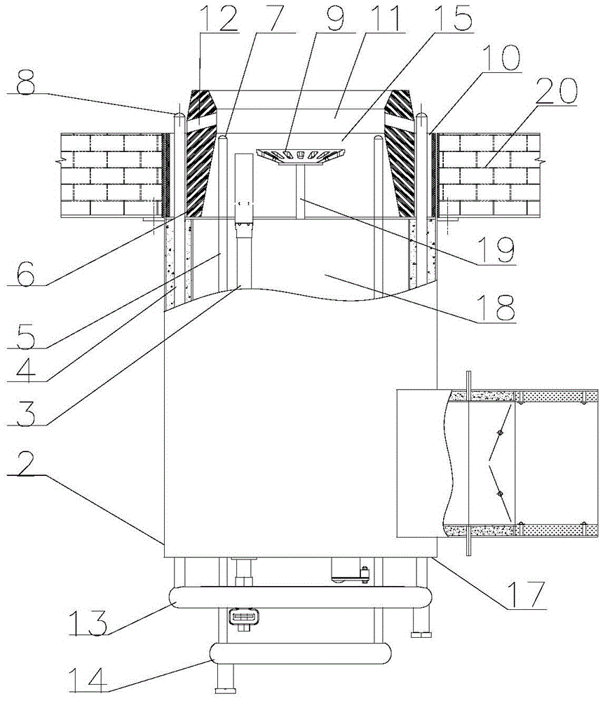
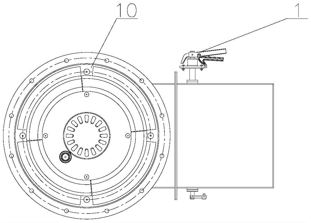
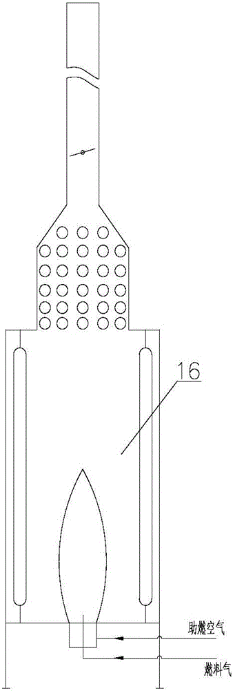
[0036] A double preheating environmental protection burner for a tubular heating furnace, the structure of which is as follows Figure 1-2 As shown, it mainly includes air duct butterfly valve 1, cylinder body 2, refractory brick 6, outer spray gun 4, inner spray gun 5, permanent lamp 3, flame stabilizing plate 9 and other parts. Set in the hearth 16 of the tube furnace, such as image 3 shown.

[0037] The burner duct butterfly valve 1 communicates with the barrel 2, and the inner passage is a high-temperature combustion air passage 19. Refractory bricks 6 are placed on the upper part of the cylinder body 2, and the internal fire channel 15 of the refractory bricks 6 is concentric with the cylinder body. A circular perforated plate, also can increase V-shaped or U-shaped folded perforated plate as required on the flame-stabilizing plate 9 . The flame stabilizing plate 9 is kept concentric with the cylinder body 2 and is located in the middle of the fire channel 14 .

[00...


PUM


Abstract

The invention relates to a double-preheating environmental protection combustor for a tube heating furnace and applications thereof. The combustor is disposed in a hearth (16) of the tube heating furnace, and comprises a cylinder (2), a firebrick (6), outer spray guns (4), and inner spray guns (5). The firebrick (6) is arranged at the upper portion of the cylinder (2). A flue (15) concentric with the cylinder (2) is formed inside the firebrick (6). The height of an outer spray gun nozzle (8) of each outer spray gun (4) is larger than the height of an inner spray gun nozzle (7) of each inner spray gun (5), and the portions, between the outer spray gun nozzles (8) and the inner spray gun nozzles (7), of the firebrick (6) are provided with firebrick inclined holes (12), so that combustion gas passing through the outer spray guns (4) and the inner spray guns (5) can burn in stages. According to the invention, a problem that a conventional combustor cannot be used for dual-preheating gas is solved, and fuel staging and flue gas multistage circulation technologies are employed, so that flame combustion high-temperature regions can be reduced, and the combustion can be stabilized.

Description

technical field [0001] The invention relates to the technical field of petrochemical tubular heating furnaces, in particular to a double preheating environmental protection burner for a tubular heating furnace and its application. Background technique [0002] Tube heating furnace is a process heating furnace used in petrochemical enterprises. In the combustion chamber surrounded by refractory materials, the heat generated by fuel combustion will heat the medium in the furnace tube to the required temperature to make it react or meet the requirements of subsequent processes. . At present, the tubular heating furnace mostly uses refinery gas or natural gas as fuel, and air is used as oxidant, and a flame is formed in the radiation chamber through a gas burner, and the medium in the radiation furnace tube and the convection furnace tube is heated in turn. In the published patent documents and industrial devices, the air is basically preheated and enters the burner to particip...

Claims


Application Information

Patent Timeline
Patent Type & Authority Applications(China)
IPC IPC(8): F23D14/22F23D14/46F23D14/66
CPCF23D14/22F23D14/46F23D14/58F23D14/66Y02E20/34
Inventor 马雷张明会
Owner 上海浩用工业炉有限公司
Why Eureka
Try Eureka