A kind of acid gas reactor and treatment process

A reactor and acid gas technology, applied in chemical instruments and methods, inorganic chemistry, sulfur compounds, etc., can solve problems such as inability to produce valuable fuming sulfuric acid, difficult operation of devices, easy deterioration of sodium sulfide, etc., to improve clarity, Avoid heat dissipation and cooling, the effect of qualified quality

Active Publication Date: 2017-07-28
CHINA PETROLEUM & CHEM CORP +1
View PDF3 Cites 0 Cited by
  • Summary
  • Abstract
  • Description
  • Claims
  • Application Information

AI Technical Summary

Problems solved by technology

[0004] The two-stage Claus + tail gas hydrogenation reduction + solvent absorption technology has mature technology, stable operation, and stable product sulfur quality. However, due to the long process and large investment, the Claus process can only deal with high-concentration acid gases. 2 When the S volume fraction is less than 20%, the device is not easy to operate
This process can only produce 98% industrial sulfuric acid, but cannot produce oleum with higher value. At the same time, due to the difficulty in the transportation and storage of sulfuric acid, the stable market demand near the refinery is an important factor limiting its development.
[0010] CN1836767A discloses a treatment method for sour gas in refineries, utilizing sour gas as the fuel for shaft kilns in cement plants, when the sour gas is burned in the kiln, the H 2 S component reacts chemically with cement material to generate CaSO 4 , other harmful components are also sintered and transformed, which fundamentally solves the problem of acid gas treatment. At the same time, acid gas is used as a gas fuel to make the cement plant energy-saving fuel and achieve the dual purposes of environmental protection and fuel resolution. However, this The method has certain limitations and is not easy to promote
However, the sodium sulfide product of this process is prone to deterioration and is not easy to store

Method used


Image

  • A kind of acid gas reactor and treatment process

Examples


Embodiment 1

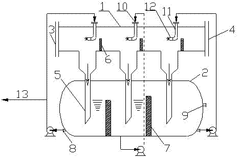
[0041] In this embodiment, the pipeline reactor is provided with 3-stage reaction sections, and the liquid storage tank is provided with 3-stage liquid storage areas.

[0042] Such as figure 1 As shown, the present invention is a schematic diagram of an acid gas treatment process, using acid gas and NaOH solution as raw materials to react and generate the acid gas treatment process of product NaHS.

[0043] The reaction process of the acid gas treatment method of the present invention is specifically described by taking the three-stage reaction section of the pipeline reactor as an example: when the pipeline reactor of the present invention is used to process acid gas, the acid gas enters the first-stage reaction section of the reaction pipeline through the gas phase inlet, and The reaction product liquid from the primary liquid storage area (the reaction product liquid from the overflow of the secondary liquid storage area, including Na 2 S and NaHS) are absorption liquids, ...


PUM


Abstract

The invention discloses an acid gas reactor. The reactor comprises a reaction pipeline and a liquid storage tank. One end of the reaction pipeline is a gas phase inlet, and the other end of the reaction pipeline is a gas phase outlet. The reaction pipeline includes more than two stages of reaction sections. The tank is set with the same number of liquid storage areas as the reaction section. Each reaction section is connected to the corresponding liquid storage area through a downcomer. Each reaction section is equipped with an absorption liquid inlet. The reaction pipe between adjacent downcomers is set. There is a partition, and an overflow plate is set on the liquid storage tank between adjacent downcomers. The lower part of each liquid storage area is equipped with a reaction liquid outlet. The reaction liquid outlet is connected to the absorption liquid inlet through a pipeline. The lye inlet is provided on the liquid area. The acid gas treatment method of the present invention uses NaOH solution as an absorption liquid to process acid gas to produce sodium hydrosulfide. Compared with the prior art, the invention achieves the dual goals of purifying acid gas and recycling pollutants.

Description

technical field [0001] The invention relates to an acid gas reactor and a treatment process, which is suitable for the field of acid gas purification, and is especially suitable for the treatment method and device for the purification of sulfur-containing hydrogen compounds and other acid gases and the recycling of pollutants. Background technique [0002] Refinery acid gas mainly comes from sour water stripping, circulating hydrogen desulfurization, dry gas desulfurization and other devices. The acid gas mainly contains H 2 S, CO 2 . At present, the acid gas in most small refineries basically adopts the treatment method of post-combustion emission. On the one hand, this method causes a waste of resources, on the other hand, it brings huge pressure to environmental protection and affects the development space of enterprises. In order to protect the environment and ensure the full utilization of resources, it is imperative to recycle the acid gas from small refineries. ...

Claims


Application Information

Patent Timeline
Patent Type & Authority Patents(China)
IPC IPC(8): B01D53/78B01D53/52C01B17/32
Inventor 彭德强乐忠辉王璐瑶王岩陈建兵孟凡飞王阳峰孟凡忠
Owner CHINA PETROLEUM & CHEM CORP
Why Eureka
Try Eureka