Piezoelectric-electromagnetic hybrid MEMS vibration energy collector and preparation method thereof

A vibration energy harvesting and composite technology, applied in piezoelectric/electrostrictive/magnetostrictive devices, piezoelectric effect/electrostrictive or magnetostrictive motors, piezoelectric devices/electrostrictive devices, etc. It can solve the problems that energy harvesters are difficult to work, limit energy collection efficiency, and low energy collection efficiency, and achieve the effect of good consistency, high energy collection efficiency, and simple and compact structure

Active Publication Date: 2015-10-28
SOUTHEAST UNIV
View PDF9 Cites 12 Cited by
  • Summary
  • Abstract
  • Description
  • Claims
  • Application Information

AI Technical Summary

Problems solved by technology

Piezoelectric and electromagnetic energy harvesters have their own advantages and disadvantages: piezoelectric energy harvesters have high output voltage but low output current; electromagnetic energy harvesters are just the opposite
However, the vibration in the environment has many and variable frequency components. Therefore, it is difficult for the energy harvester to work in a resonant state in practice, and its energy harvesting efficiency is low; in addition, the traditional piezoelectric and electromagnetic energy harvesting The device can only collect vibration energy in a single direction. When working in an environment where the vibration direction changes randomly, the vibration energy it can collect is very limited, which further limits its energy collection efficiency.

Method used


Image

  • Piezoelectric-electromagnetic hybrid MEMS vibration energy collector and preparation method thereof
  • Piezoelectric-electromagnetic hybrid MEMS vibration energy collector and preparation method thereof
  • Piezoelectric-electromagnetic hybrid MEMS vibration energy collector and preparation method thereof

Examples


Embodiment Construction

[0037] A preparation method of a piezoelectric-electromagnetic composite MEMS vibration energy harvester, comprising the steps of:

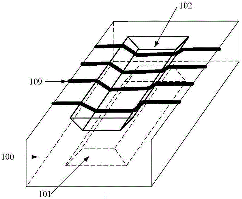
[0038] (1), select N-type (100) silicon as the first substrate 100, and grow SiO with a thickness of 500 nm on the upper surface and the lower surface of the first substrate 100 by wet oxygen thermal oxidation. 2 .

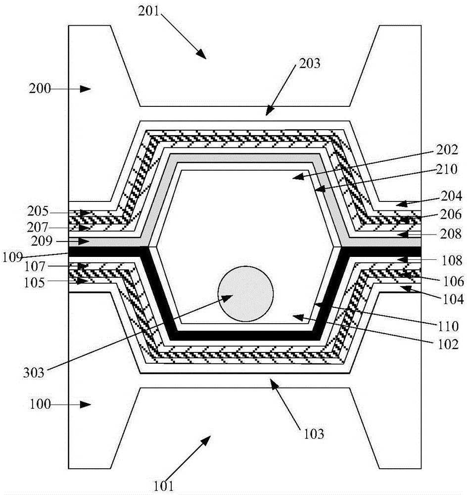
[0039] (2), with SiO on the upper and lower surfaces of the first substrate 2 Make a mask and use TMAH (Tetramethyl ammonium hydroxide, tetramethylammonium hydroxide) reagent to perform anisotropic wet etching on the upper surface and the lower surface of the first substrate respectively, the etching depth is 100-300 μm, after etching A first groove 101 is formed in the middle of the lower surface of the first substrate, a second groove 102 is formed in the middle of the upper surface, and the silicon substrate region between the bottom of the first groove 101 and the bottom of the second groove 102 forms a second groove. A square ...


PUM

PropertyMeasurementUnit
depthaaaaaaaaaa
thicknessaaaaaaaaaa
thicknessaaaaaaaaaa

Abstract

The present invention discloses a piezoelectric-electromagnetic hybrid MEMS vibration energy collector and a preparation method thereof. A movable permanent magnet is used as a pick-up structure. Under the effect of a vibration environment, the movable permanent magnet moves in a cavity, thus the magnetic flux in a spiral inductance coil is changed, induction current is generated in a closed loop formed by the spiral inductance coil and an external load, and the conversion of vibrational energy into electrical energy through an electromagnetic induction mode is realized. In addition, when the movable permanent magnet moves in the cavity, the generated pressure or impact causes the bending deformation of a first square film or a second square film, the deformation of a piezoelectric layer is caused to generate piezoelectric voltage, the conversion of the vibrational energy into the electrical energy through a piezoelectric effect is realized, and the piezoelectric electrode of the piezoelectric layer is connected to supply power to the load. According to the piezoelectric-electromagnetic hybrid MEMS vibration energy collector and the preparation method, the modes of electromagnetic induction and piezoelectric effect are combined to convert the vibrational energy into the electrical energy, and the electromagnetic induction and the piezoelectric effect are superimposed to supply power to the load.

Description

technical field [0001] The present invention relates to an energy harvester for collecting vibration energy in the environment and a preparation method thereof, in particular to a piezoelectric-electromagnetic composite vibration energy harvester based on MEMS (Micro-Electro-Mechanical System, Micro-Electro-Mechanical System) technology and its preparation method. Background technique [0002] The Internet of Things has broad application prospects in the fields of national economy and people's livelihood such as intelligent transportation, medical health, environmental monitoring, public security, national defense and military affairs. my country has vigorously promoted the Internet of Things as a strategic industry. Micro-energy technology is responsible for providing power to the sensor nodes of the Internet of Things, and is one of the key technologies for the development of the Internet of Things. At present, micro energy sources such as chemical energy batteries or fue...

Claims


Application Information

Patent Timeline
Patent Type & Authority Applications(China)
IPC IPC(8): H02N2/18H02K35/02B81C1/00B81B3/00
Inventor 黄晓东黄见秋黄庆安
Owner SOUTHEAST UNIV
Why Eureka
Try Eureka