Free-space optical micro-cavity Raman laser sensing device and sensing method thereof

An optical microcavity and Raman laser technology, which is applied in the direction of transmitting sensing components, optics, lasers, etc. by using optical devices, can solve the problems of easy breakage of optical fiber cones, reduction of signal-to-noise ratio, and changes, so as to reduce the detection limit, The effect of increasing flexibility and reducing the signal-to-noise ratio

Active Publication Date: 2015-11-04
PEKING UNIV
View PDF4 Cites 11 Cited by
  • Summary
  • Abstract
  • Description
  • Claims
  • Application Information

AI Technical Summary

Problems solved by technology

[0003] In the Raman laser sensing technology that excites the whispering gallery mode of the optical microcavity through the evanescent wave of the fiber cone, there are three main technical problems that cannot be avoided: first, in order to ensure the coupling efficiency between the fiber cone and the optical microcavity, The distance between the two needs to be strictly controlled, and the nanoscale size of the fiber cone makes it extremely susceptible to the influence of the surrounding environment, such as air flow, temperature c

Method used


Image

  • Free-space optical micro-cavity Raman laser sensing device and sensing method thereof
  • Free-space optical micro-cavity Raman laser sensing device and sensing method thereof
  • Free-space optical micro-cavity Raman laser sensing device and sensing method thereof

Examples


Embodiment 1

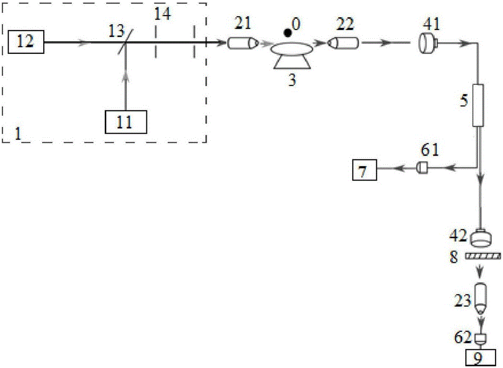
[0041] like figure 2 As shown, the free space optical microcavity Raman laser sensing device of this embodiment includes: a laser light source 1, a first focusing objective lens 21, an optical microcavity 3, a second focusing objective lens 22, a first collimating lens 41, an optical fiber splitter The beam filter 5, the first photodetector 61, the oscilloscope 7, the second collimating lens 42, the long-pass filter 8, the third focusing objective lens 23, the second photodetector 62 and the fundamental spectrum analyzer 9; Nano-sized particles 0 are attached to the surface of the microcavity 3 .

[0042] In this embodiment, the optical microcavity adopts a non-rotationally symmetric dielectric solid body, such as a deformed micro-core ring, a deformed spherical cavity, etc., which supports a high-quality whispering gallery mode, which can realize directional laser output, and the dielectric optical microcavity There can be one or more incoming and outgoing light directions....

Embodiment 2

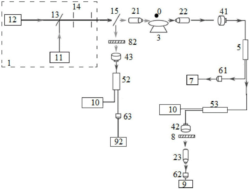
[0045] like image 3 As shown, in this embodiment, a triangular prism 15 is added between the light source 1 and the first focusing objective lens 21, and the Raman laser of the optical microcavity 3 attached with the nano-sized particles 0 is excited in the whispering gallery mode; Opposite the direction of the incident light, return along the direction opposite to the direction of the incident light, and collect the reverse outgoing light by the first focusing objective lens 21 to the triangular prism 15. The reverse outgoing light includes laser, whispering gallery mode and Raman laser; reverse The outgoing light is reflected by the prism 15 to the second long-pass filter 82 to filter out the laser and the whispering gallery mode, and then enters the second fiber beam splitter 52 through the third collimating lens 43, and 30% of the optical signal is collected by the spectrometer 10 and analyzed. The wavelength of the Raman laser; the other 70% of the optical signal enters ...

Embodiment 3

[0047] In Example 1 and Example 2, the wavelength range of the whispering gallery mode is obtained and the outgoing light in the same outgoing light direction is collected by analyzing the Raman laser beat frequency. In this embodiment, outgoing light in different outgoing light directions is collected.

[0048] like Figure 4 As shown, the free-space optical microcavity Raman laser sensing device of this embodiment includes: a laser light source 1, a first focusing objective lens 21, an optical microcavity 3, a second focusing objective lens 22, a first collimating lens 41, a second The collimating lens 42 , the first photodetector 61 , the oscilloscope 7 , the long pass filter 8 , the third focusing objective 23 , the second photodetector 62 and the fundamental spectrum analyzer 9 . The broadband tunable frequency laser 11 provides a broadband frequency sweep laser, and the laser is coupled into the optical microcavity 3 through the first focusing objective lens 21 through t...


PUM


Abstract

The invention discloses a free-space optical micro-cavity Raman laser sensing device and a sensing method thereof. The sensing device comprises a laser light source, a first focusing object lens, an optical micro-cavity, a second focusing object lens, a first collimating lens, a second collimating lens, a first photoelectric detector, an oscilloscope, a filter sheet, a third focusing object lens, a second photoelectric detector and a base spectrum analyzer. Raman laser of an optical micro-cavity is triggered through free-space frequency-tunable laser, and by observing frequency of beat frequency of the Raman laser, information of nanoscale-dimension particles attached to the surface of the optical micro-cavity is obtained; in the free-space Raman laser sensing technology, a whispering gallery mode and the Raman laser can be directly triggered in the free space through the frequency-tunable laser; and through avoiding the technical problems due to the introduction of an optical fiber taper, the flexibility of the device is improved, and signal to noise ratio is reduced, so that sensitivity of the sensing device is improved, and detection limit is reduced.

Description

technical field [0001] The invention relates to Raman laser sensing technology, in particular to a free space optical microcavity Raman laser sensing device and a sensing method thereof. Background technique [0002] Existing optical microcavity Raman laser sensing technology excites whispering gallery modes by coupling evanescent waves into optical microcavities through fiber cones, such as figure 1 As shown in the figure, the Raman laser is excited by the whispering gallery mode. When there are nano-sized particles adsorbed on the surface of the optical microcavity, the frequency of the Raman laser beat frequency changes, and the information of the nano-sized particles is interpreted from this change. The optical fiber cone is drawn from ordinary optical fiber. First, the protective layer of the ordinary optical fiber is removed and transferred to a movable platform. The optical fiber is melted by a hydrogen-oxygen flame, and then a fiber cone with a diameter of 100 nanome...

Claims


Application Information

Patent Timeline
IPC IPC(8): H01S3/10G01D5/26G02F1/39
Inventor 肖云峰郅燕燕龚旗煌
Owner PEKING UNIV
Why Eureka
Try Eureka