Novel flame retardant, heat insulation and heat preservation material structure

A technology of thermal insulation and material structure, which is applied in the direction of protecting pipelines through thermal insulation, thermal insulation, thermal insulation, etc., can solve the problems of poor flame retardancy, short thermal insulation life, low thermal insulation effect, etc., and achieves good flame retardant performance and flame retardant performance. Increase, good shock absorption effect

Inactive Publication Date: 2015-11-11
SUZHOU HONGJIU AVIATION THERMAL MATERIALS TECH CO LTD
View PDF9 Cites 12 Cited by
  • Summary
  • Abstract
  • Description
  • Claims
  • Application Information

AI Technical Summary

Problems solved by technology

[0005] The purpose of the present invention is to overcome the shortcomings of the existing thermal insulation materials such as short thermal

Method used


Image

  • Novel flame retardant, heat insulation and heat preservation material structure
  • Novel flame retardant, heat insulation and heat preservation material structure

Examples


Embodiment 1

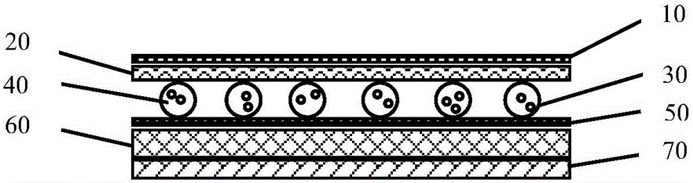
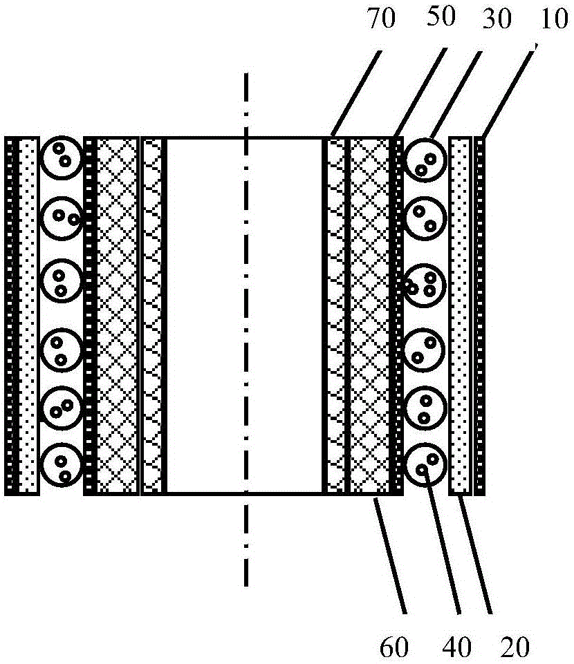
[0013] A new type of flame-retardant heat-insulating material structure, which is characterized in that it sequentially includes a first aluminum foil layer, a woven cloth layer, sac-shaped air cells, a second aluminum foil layer, melamine foam, and airgel felt; the sac-shaped air cells are filled with Flame retardant inert gas; nano flame retardant particles are added in the bubble layer, the bubble height is 2mm, and the width is 3mm; the thickness of the melamine foam is 2mm, and the porosity in the foam is 90%; the airgel felt The thickness is 8mm.

[0014] The first aluminum foil layer, the woven cloth layer, the sac-shaped air bubbles, and the second aluminum foil layer are bonded by a polyurethane adhesive, with a thickness of 30mm; the second aluminum foil layer, the melamine foam is bonded by PA- 80 adhesive bonding, the thickness is 30 mm; the melamine foam and the airgel felt are bonded by acrylic adhesive, and the thickness is 35 mm.

[0015] The structure of the ...

Embodiment 2

[0017] A new type of flame-retardant heat-insulating material structure, which is characterized in that it sequentially includes a first aluminum foil layer, a woven cloth layer, sac-shaped air cells, a second aluminum foil layer, melamine foam, and airgel felt; the sac-shaped air cells are filled with Flame retardant inert gas; nano flame retardant particles are added in the bubble layer, the bubble height is 16mm, and the width is 30mm; the thickness of the melamine foam is 10mm, and the porosity in the foam is 97%; the airgel felt The thickness is 15mm.

[0018] The first aluminum foil layer, woven cloth layer, sac-shaped air bubbles, and the second aluminum foil layer are bonded by a polyurethane adhesive, with a thickness of 50 mm; the second aluminum foil layer, melamine foam is bonded by PA- 80 adhesive bonding, the thickness is 55mm; the melamine foam and the airgel felt are bonded by acrylic adhesive, and the thickness is 65mm.


PUM

PropertyMeasurementUnit
Thicknessaaaaaaaaaa
Thicknessaaaaaaaaaa
Thicknessaaaaaaaaaa

Abstract

A novel flame retardant, heat insulation and heat preservation material structure is characterized by comprising a first aluminum foil layer, a weaved cloth layer, cystic bubbles, a second aluminum foil layer, melamine foam and an aerogel felt; the cystic bubbles are filled with flame retardant inert gas; nanometer flame retardant particles are added in the bubble layer, the height of the bubbles ranges from 2 to 16 mm, and the width of the bubbles ranges from 3 to 30 mm; the thickness of the melamine foam ranges from 2 to 10 mm, and the gas hole ratio of the foam ranges from 90% to 97%; the thickness of the aerogel felt ranges from 8-15 mm; the first aluminum foil layer, the weaved cloth layer, the cystic bubbles and the second aluminum foil layer are bonded through polyurethanes binding agents, and the thickness ranges from 30 to 50 mm; the second foil layer and the melamine foam are bonded through PA-80 binding agents, and the thickness ranges from 30 to 55 mm; the melamine foam and the aerogel felt are bonded through crylic acid binding agents, and the thickness ranges from 35 to 65 mm. The heat preservation material can be applied horizontally or made into pipes for use, the flame retardant property is good, the damping effect is good, the weight is low, and the heat preservation and energy conservation effects are ideal.

Description

technical field [0001] The invention relates to a thermal insulation material structure, in particular to a flame-retardant and heat-insulating thermal insulation material structure. Background technique [0002] In the general environment of the global low-carbon economy, the development of environmental protection and energy-saving materials is one of the key links. At present, the heat insulation materials commonly used in the market are mostly polyurethane foam, EPE foam or non-woven fabric and aluminum foil composite materials, etc. These materials have poor shock absorption performance and weak corrosion and aging resistance, which reduces their service life. After about two years of use, its thermal insulation and waterproof function disappears; again, these materials are poor in flame retardancy and have potential safety hazards. At present, the heating pipeline generally has the problems of large heat loss and low thermal efficiency. Traditional insulation methods...

Claims


Application Information

Patent Timeline
IPC IPC(8): E04B1/76E04B1/94F16L59/02F16L59/08B32B15/14B32B15/16B32B15/098B32B27/12B32B15/095
CPCY02A30/00Y02B30/90
Inventor 陈照峰王伟伟
Owner SUZHOU HONGJIU AVIATION THERMAL MATERIALS TECH CO LTD
Why Eureka
Try Eureka