Water treatment device combining multiple physical methods
A technology of water treatment device and physical method, applied in the field of water treatment
- Summary
- Abstract
- Description
- Claims
- Application Information
AI Technical Summary
Problems solved by technology
Method used
Image
Examples
Embodiment 1
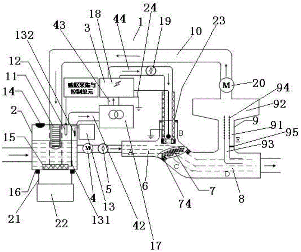
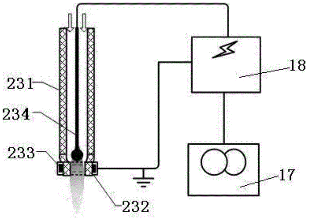
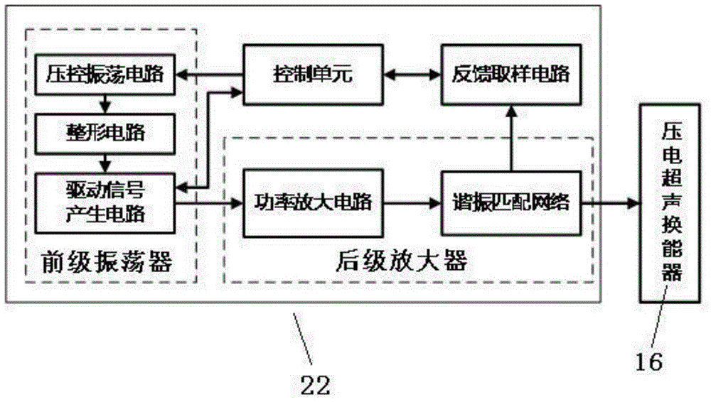
[0063] like Figure 1~12 As shown, the multi-physical method combined water treatment device is characterized in that: it includes: a water treatment unit 1, the water treatment unit 1 includes an ultrasonic ultraviolet ozone combined reactor 2 and a plasma generator 3, and the ultrasonic ultraviolet ozone combined reaction The water outlet of the device 2 is connected to the water inlet of the Y-shaped reactor 6 through the liquid pump 4 and the liquid flow meter 5, and the gas outlet of the plasma generator 3 extends into the inside of the air inlet of the Y-shaped reactor 6, The water outlet of the Y-shaped reactor 6 is arranged below the water inlet and the air inlet of the Y-shaped reactor 6, and the water outlet of the Y-shaped reactor 6 is provided with a mesh 7 of loaded catalysts. The water outlet of the Y-shaped reactor 6 is connected with the water outlet pipe 8 in the horizontal direction, and the side wall of the water outlet pipe 8 is connected with the air inlet...
Embodiment 2
[0093] like Figure 1~12 As shown, the multi-physics combined water treatment device is characterized in that: the diameter of the circular inner hole network 72 is 20mm smaller than the diameter of the outer ring 71, and the bandwidth of the strip 73 is 4mm. The diameter of several evenly distributed circular holes on the circular inner hole network 72 is 1.5mm; the catalyst-loaded hole network 7 is set at an angle α to the horizontal plane, and the α is 35°.
[0094] The catalyst-loaded mesh 7 is located below the dielectric barrier discharge jet nozzle 23, and the vertical distance between the gas outlet of the dielectric barrier discharge jet nozzle 23 and the catalyst-loaded hole mesh 7 is d, and the The vertical distance between the gas outlet of the dielectric barrier discharge jet nozzle 23 and the hole network 7 of the loaded catalyst is D, and D is 18mm, and the gas outlet of the dielectric barrier discharge jet nozzle 23 is vertically inserted into the inlet of the ...
PUM
 Abstract
Description
Claims
Application Information
 - R&D
- Intellectual Property
- Life Sciences
- Materials
- Tech Scout
- Unparalleled Data Quality
- Higher Quality Content
- 60% Fewer Hallucinations
Browse by: Latest US Patents, China's latest patents, Technical Efficacy Thesaurus, Application Domain, Technology Topic, Popular Technical Reports.
© 2025 PatSnap. All rights reserved.Legal|Privacy policy|Modern Slavery Act Transparency Statement|Sitemap|About US| Contact US: help@patsnap.com


