Oxygen enriching and magnetizing device of air duct of internal combustion engine

A technology of magnetization device and air intake channel, which is applied in the direction of internal combustion piston engine, combustion air/combustion-air treatment, combustion engine, etc., can solve the problem of insufficient combustion of the mixture gas of internal combustion engine, and achieve the problem of sluggish start and increase the combustion rate , the effect of particle reduction

Inactive Publication Date: 2015-11-18
嘉兴市健杰内燃机零件有限公司
View PDF11 Cites 4 Cited by
  • Summary
  • Abstract
  • Description
  • Claims
  • Application Information

AI Technical Summary

Problems solved by technology

[0003] In order to solve the above technical problems, the present invention designs an oxygen enrichment and magnetization device for the intake port of an internal combustion engine to solve the problem of insufficient combustion of the mixture gas in the existing internal combustion engine

Method used


Image

  • Oxygen enriching and magnetizing device of air duct of internal combustion engine
  • Oxygen enriching and magnetizing device of air duct of internal combustion engine
  • Oxygen enriching and magnetizing device of air duct of internal combustion engine

Examples


Embodiment 1

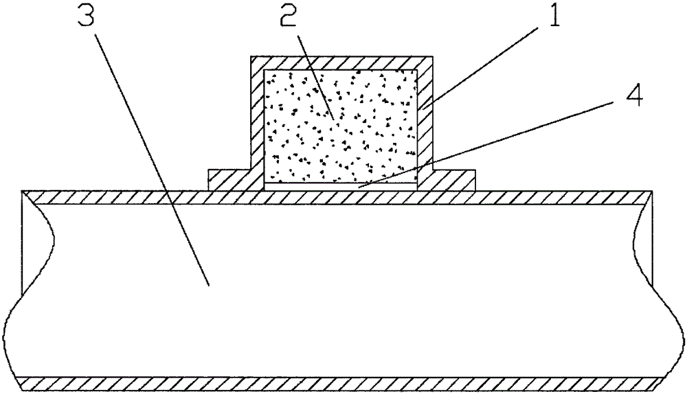
[0028] Embodiment one: if figure 1 Shown:

[0029] The device can be installed outside the pipeline 3 through an external installation method. The device includes a permanent magnetic material 2 and a magnetic isolation cover 1. The permanent magnetic material 2 is wrapped in the magnetic isolation cover 1. There is a side surface on the magnetic isolation cover 1. The magnetic force acting surface 4 formed by the gap.

[0030] The permanent magnet material 2 can be samarium cobalt, neodymium iron boron, samarium iron nitrogen or electromagnet, but not limited to these materials.

[0031] The magnetic field strength of the permanent magnet material 2 is 10MT to 1500MT.

[0032] The operating temperature of the device is -40°C to 250°C.

[0033] The magnetic isolation cover 1 can affect the magnetic field distribution of the permanent magnet material, isolate the magnetic fields in other directions, and strengthen the magnetic field strength on the opening acting surface lef...

Embodiment 2

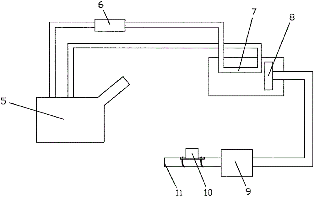
[0036] Embodiment two: if Figure 4 Shown:

[0037] The device includes a permanent magnetic material 2 and a magnetic isolation cover 1. The permanent magnetic material 2 is wrapped in the magnetic isolation cover 1. The magnetic isolation cover 1 is provided with a magnetic force acting surface 4 formed by a gap. The device can pass through a semi-embedded The installation method is that one part is installed inside the pipeline 3 and the other part is installed outside the pipeline 3 . The rest of the structure of the device is the same as in Embodiment 1.

Embodiment 3

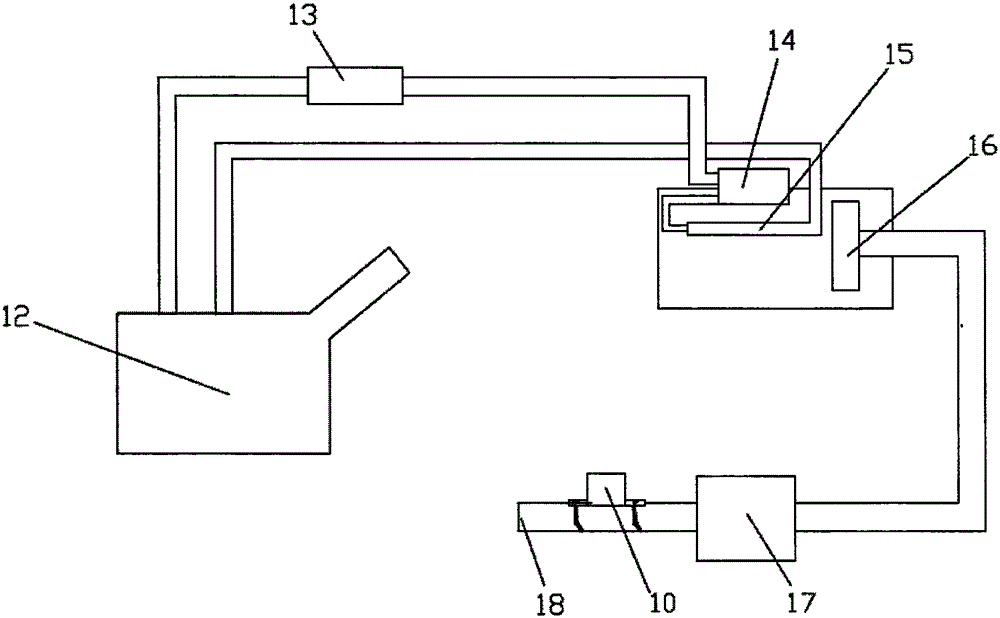
[0038] Embodiment three: as Figure 5 Shown:

[0039] The device includes a permanent magnetic material 2 and a magnetic isolation cover 1, the permanent magnetic material 2 is wrapped in the magnetic isolation cover 1, and the magnetic isolation cover 1 is provided with a magnetic force acting surface 4 formed by a gap. The device can be installed inside the pipeline 3 through a built-in installation method, and the rest of the structure of the device is the same as that of the first embodiment.


PUM


Abstract

The invention relates to an oxygen enriching and magnetizing device of an air duct of an internal combustion engine. The device comprises a permanent magnet material and a magnetism isolation cover. The permanent magnet material is wrapped in the magnetism isolation cover. The magnetism isolation cover is provided with a magnetic action face formed by gaps. The device is arranged at any position from the front end of a gasoline air intake inlet to a throttle valve of the internal combustion engine passing through a gasoline air cleaner and a turbocharger. The device is arranged at any position from a diesel air intake inlet to a diesel air intake manifold passing through a diesel air cleaner and the turbocharger. According to the oxygen enriching and magnetizing device, the oxygen in the air is enriched, so that the combustion rate of the internal combustion engine is improved, the utilization rate of thermal efficiency of the internal combustion engine is increased, the effective power of the internal combustion engine is improved, exhaust gas emission is lowered, the work noise of the internal combustion engine is lowered, energy consumption is lowered, accumulated carbon in a combustion chamber is cleared to protect the internal combustion engine, and the service life of the internal combustion chamber is prolonged.

Description

technical field [0001] The present invention relates to the field of internal combustion engines, in particular to internal combustion engines for road transport (gasoline engine vehicles, diesel engine vehicles, natural gas vehicles, ethanol fuel vehicles, methanol fuel vehicles), internal combustion engines for non-road transport (generator sets, ships, engineering machinery, drilling rigs, Oil-fired boilers) and the oil passages and air intakes of all equipment using fuel oil, natural gas, ethanol fuel, and methanol fuel. Background technique [0002] It is well known that the oxygen (O 2 ) is provided directly by the air, while oxygen accounts for only 20% in the air, and most of the rest is nitrogen (N 2 ) and a trace amount of rare gas, the cylinder volume is limited (invariable), and the oxygen (O 2 ) remains unchanged, coupled with the limitation of the formation speed and quality of the mixed gas, so that part of the mixed gas in the cylinder cannot be completely ...

Claims


Application Information

Patent Timeline
Patent Type & Authority Applications(China)
IPC IPC(8): F02M27/04
CPCY02T10/12
Inventor 罗建斌姚杰张锋锐姚伟冰
Owner 嘉兴市健杰内燃机零件有限公司
Why Eureka
Try Eureka