
Heat exchange method for low-temperature regenerative catalytic oxidation treatment device

A catalytic oxidation and treatment device technology, applied in combustion methods, incinerators, lighting and heating equipment, etc., can solve the problems of high safety hazards, high ignition temperature, high energy consumption, etc., and achieve high safety and high device efficiency , the effect of high processing index

Active Publication Date: 2017-09-22
CHINA PETROLEUM & CHEM CORP +1
View PDF8 Cites 0 Cited by
  • Summary
  • Abstract
  • Description
  • Claims
  • Application Information

AI Technical Summary

Problems solved by technology

[0006] The technical problem to be solved by the present invention is the problem of large potential safety hazard, high light-off temperature, and high energy consumption in the prior art. It provides a new heat exchange method for a low-temperature regenerative catalytic oxidation treatment device

Method used


Image

  • Heat exchange method for low-temperature regenerative catalytic oxidation treatment device
  • Heat exchange method for low-temperature regenerative catalytic oxidation treatment device

Examples


Embodiment 1

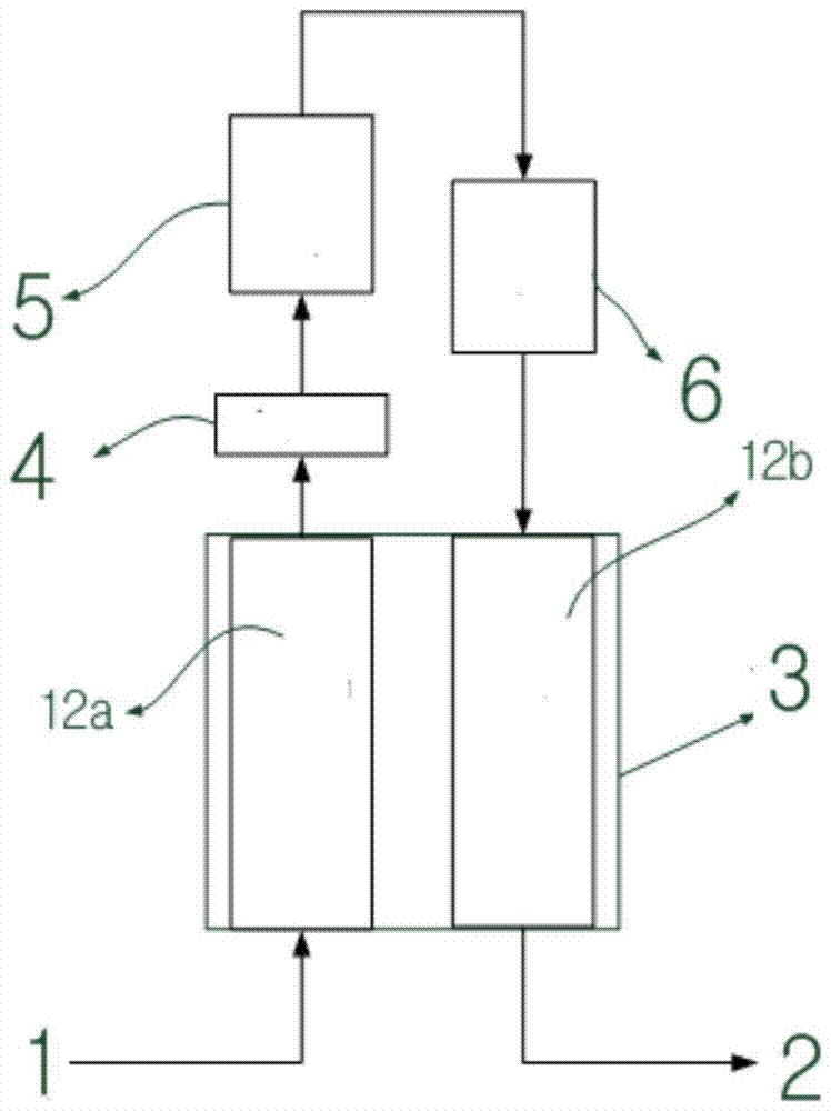
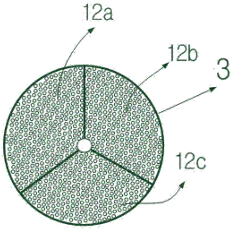
[0019] as per figure 1 In the process shown, the VOCs gas that has been recovered and pretreated enters the cold process of the rotary honeycomb ceramic regenerator, and then enters the low-temperature oxidation bed after being heated in the heating chamber. More than 90% of the VOCs gas has been in the low-temperature catalytic oxidation bed. is decomposed into CO 2 and H 2 O, release heat at the same time and enter the high-temperature catalytic oxidation bed. At the same time, when the gas temperature is high at this time, the pretreatment system increases the dilution force to reduce the combustion temperature of VOCs gas.

[0020] The high-temperature catalytic oxidation bed is filled with a noble metal Pt high-temperature catalyst different from the low-temperature catalytic oxidation bed, and the required working temperature of the catalyst is higher than that required by the low-temperature catalytic oxidation bed. The remaining small part of VOCs gas is further deco...

Embodiment 2

[0025] According to the conditions and steps described in Example 1, the reaction temperature of the low-temperature catalytic oxidation bed is 200°C. The reaction temperature of the high temperature catalytic oxidation bed is 420°C. The catalyst in the low-temperature catalytic oxidation bed is nano-silver / manganese oxide / cerium oxide supported honeycomb ceramic catalyst, and the mass content of nano-silver / manganese oxide / cerium oxide is 60g / L, 10g / L, 10g / L respectively; the high-temperature catalytic oxidation bed The catalyst inside is a supported Pt catalyst, and the Pt supported mass content is 2.5g / L.

[0026] Take the oil and gas volatilized from gasoline as an example, the import concentration is 50g / m 3 Normal temperature gasoline oil gas, the concentration is diluted to 5.5g / m after system pretreatment 3 (25% of the lower limit of the explosion limit is 9.4g / m 3 ), which is lower than 25% of the lower limit of the explosion limit. After heat exchange by the heat ...


PUM


Abstract

The invention relates to a heat exchange method for a low-temperature heat accumulating type catalytic oxidation treatment device. The problems that in the prior art, serious potential safety hazards exist, ignition temperature is high, and energy consumption is large are mainly solved. The heat exchange method for the low-temperature heat accumulating type catalytic oxidation treatment device is adopted, VOCs gas with the concentration lower than 25% of an explosion limit enters a cold stroke of a rotary type honeycomb ceramic heat accumulator, and then enters a heating chamber to be heated; heated gas enters a low-temperature catalytic oxidation bed to be in contact with nano-silver or nano-silver / manganese oxide / cerium oxide loaded honeycomb ceramic catalysts, and then gas enters a high-temperature catalytic oxidation bed to be in contact with a Pt or Pd loaded noble metal catalyst; and after heat is released, gas enters a hot stroke of the rotary type honeycomb ceramic heat accumulator to be subjected to further high-temperature combustion in the rotary type honeycomb ceramic heat accumulator, and the treatment efficiency of above 99% is achieved. According to the technical scheme, the problems are solved well, and the method can be used for the low-temperature heat accumulating type catalytic oxidation treatment device.

Description

technical field [0001] The invention relates to a heat exchange method for a low-temperature regenerative catalytic oxidation treatment device. Background technique [0002] At present, there are two main types of treatment technologies for volatile organic compounds (VOCs): one is recovery technology, and the other is destruction technology. Recovery technology is a method of enriching and separating organic gas phase pollutants through physical methods, such as changing temperature and pressure or using selective adsorbents and selective permeable membranes, mainly including adsorption technology, absorption technology, condensation technology and membrane separation technology . The destruction technology mainly uses heat, light, catalysts and microorganisms to convert organic compounds into non-toxic or low-toxic inorganic small molecule compounds such as carbon dioxide and water through chemical or biochemical projections. Catalytic oxidation, plasma destruction, etc....

Claims


Application Information

Patent Timeline
Patent Type & Authority Patents(China)
IPC IPC(8): F23G7/07
CPCF23G7/07F23G2209/14
Inventor 王林尹树孟张丽萍
Owner CHINA PETROLEUM & CHEM CORP
Learn More