Roll production method and roll produced by the method

A production method and roll technology, applied in other manufacturing equipment/tools, turbines, engine components, etc., can solve the problem of segregation of carbides in composite joints, shrinkage and porosity of bushings, and uneven structure and composition. and other problems, to achieve the effect of tight bonding, reduced hardness, and no segregation of the organization.

Inactive Publication Date: 2017-12-08
飞而康快速制造科技有限责任公司
View PDF1 Cites 0 Cited by
  • Summary
  • Abstract
  • Description
  • Claims
  • Application Information

AI Technical Summary

Problems solved by technology

[0009] Therefore, the technical problem to be solved by the present invention is to overcome the low bonding strength of the composite interface between the roll sleeve and the mandrel in the composite roll produced by the prior art, uneven structure and composition, easy generation of shrinkage cavities and looseness in the sleeve, and the failure of the roll sleeve. The composite junction with the mandrel is prone to carbide segregation and low service life, so as to provide a roller sleeve with high bonding strength, uniform structure and composition, and no shrinkage and porosity in the shaft sleeve. Method for long-life roll without segregation of carbides in composite joint with mandrel
[0010] In addition, the technical problem to be solved by the present invention is to overcome the low bonding strength of the composite interface between the sleeve and the mandrel in the composite roll in the prior art, uneven structure and composition, easy shrinkage and porosity in the sleeve, and problems between the sleeve and the mandrel. The composite junction of the mandrel is prone to segregation of carbides and low service life, so as to provide a production method with high bonding strength, uniform structure and composition, no shrinkage cavity and porosity in the shaft sleeve, roller sleeve and High-life roll with no carbide segregation at the composite joint of the mandrel

Method used


Image

  • Roll production method and roll produced by the method
  • Roll production method and roll produced by the method

Examples


Embodiment 1

[0036] This embodiment provides a roll production method, comprising:

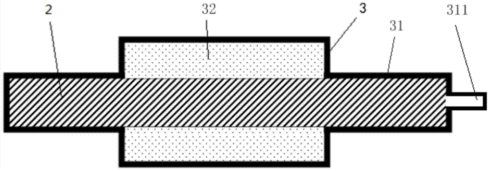
[0037] S1: Set a sheath 3 with an air port 311 outside the mandrel 2, and put alloy powder into the sheath 3 when setting, the sheath 3, such as figure 1 As shown, there are end portions 31 matching the diameter of the mandrel 2 at both ends in the axial direction, and an intermediate portion 32 for accommodating alloy powder is provided between the two end portions 31, and the intermediate portion 32 is connected to the An accommodating space for alloy powder is formed between the mandrels 2, and an air port 311 is formed on one of the ends 31. The alloy powder is prepared by an argon atomization method. The composition of the alloy powder is shown in Table 1. After the alloy powder is added to the sheath 3, it is filled in the sheath by vibration. The material of the sheath 3 is stainless steel, and the material of the mandrel 2 is low-cost ductile iron;

[0038] S2: Degas the alloy powder in the sheath...

Embodiment 2

[0043] This embodiment provides a roll production method. The difference from Embodiment 1 is that the composition of the alloy powder is different. The composition of the alloy powder is shown in Table 1, and the heat treatment process in the S5 step is different. In the S5 step, the annealing treatment is, The annealing temperature is 880°C, and the annealing holding time is 3 hours. When the temperature is lowered, the temperature is higher than 700°C, and the cooling rate is 10°C / h. After the temperature is lower than 700°C, it is cooled with the furnace. Quenching and tempering treatment is as follows: preheating temperature is 880°C, quenching temperature is 1100°C, high temperature tempering is carried out twice after quenching, and tempering temperature is 540°C.

Embodiment 3

[0045] This embodiment provides a roll production method. The difference from Embodiment 1 is that the composition of the alloy powder is different. The composition of the alloy powder is shown in Table 1, and the heat treatment process in the S5 step is different. In the S5 step, the annealing treatment is, The annealing temperature is 900°C, and the annealing holding time is 4 hours. When the temperature is lowered, the temperature is higher than 700°C, and the cooling rate is 11°C / h. After the temperature is lower than 700°C, it is cooled with the furnace. Quenching and tempering treatment is as follows: preheating temperature 900°C, quenching temperature 1200°C, high temperature tempering three times after quenching, tempering temperature 500°C.


PUM


Abstract

The invention relates to a production method of a roll, comprising: S1: setting a sheath with a gas port outside the mandrel, and loading alloy powder into the sheath when setting; S2: extracting gas from the gas port on the sheath to The alloy powder in the sheath is degassed; S3: seal the gas port to form a transition piece; S4: hot isostatically press the whole sheath containing the mandrel inside, so that the alloy powder is sintered to form a roller sleeve; S5 : Remove the sheath and perform machining to form a roll that meets the required size and surface quality. For the roll obtained by the roll production method of the present invention, the joint between the mandrel and the roll sleeve is a metallurgical joint interface, the joint is tight, no carbide is precipitated at the joint, and the content of non-metallic inclusions in the roll sleeve is low. There is no segregation in the structure of the roller sleeve, and the composition distribution is more uniform. At the same time, the surface hardness of the roller sleeve is uniform, and the surface quality of the product is greatly improved. Finally, the service life of the roll is greatly improved.

Description

technical field [0001] The invention relates to a roll production method and a roll produced by the method, belonging to the technical field of metallurgical machinery and equipment. Background technique [0002] The roll is an indispensable key component and the most important consumable spare part in the production of the metallurgical industry. The quality of the roll has an important impact on the production cost, processing efficiency and the quality of the rolled parts. For hot-rolled rolls, since they need to be in contact with hot-rolled steel at about 1200°C during work, the surface temperature of the rolls is very high, so the rolls need to maintain high hardness, high strength and good wear resistance at high temperatures. At present, a variety of materials for making rolls have been developed at home and abroad. Commonly used materials include alloy ductile iron, bainite ductile iron, high-chromium cast iron, high-vanadium cast iron, high-boron alloy, tool steel,...

Claims


Application Information

Patent Timeline
Patent Type & Authority Patents(China)
IPC IPC(8): B22F3/15B22F5/00C22C38/30C21D1/25
Inventor 刘慧渊张岳香
Owner 飞而康快速制造科技有限责任公司
Why Eureka
Try Eureka