
Cloud particle detection method and cloud particle detector

A cloud particle detection and cloud particle technology, which is applied in the field of cloud particle detection and detectors, can solve the problems of particle merger, inability to distinguish individual particles, and slow processing speed of the camera to achieve the effect of convenient detection

Inactive Publication Date: 2015-12-02
NANJING UNIV OF INFORMATION SCI & TECH
View PDF4 Cites 22 Cited by
  • Summary
  • Abstract
  • Description
  • Claims
  • Application Information

AI Technical Summary

Problems solved by technology

Cotton reported in 2010 that the second-generation ice crystal detector SID-2 uses custom-made phase function detectors (32 detectors) distributed in concentric circles. The sensitivity of the detector has also been greatly improved, but when the cloud particle concentration exceeds 20 / cm 3 When , SID-2 cannot distinguish individual particles
The third-generation SID-3 uses a high-resolution camera to perform two-dimensional imaging of the stripes to obtain high angular resolution. However, due to the slow processing speed of the camera, when the concentration of ice crystal particles is large, particle mergers occur, and the measured particle number is less than Actual number of particles
Therefore, the detection of small ice crystals (less than 50 μm) in ice clouds or mixed-phase clouds is still an unsolved problem

Method used


Image

  • Cloud particle detection method and cloud particle detector
  • Cloud particle detection method and cloud particle detector
  • Cloud particle detection method and cloud particle detector

Examples


Embodiment 1

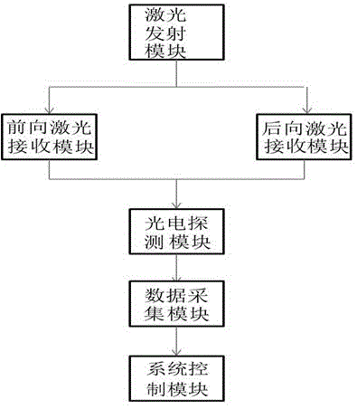
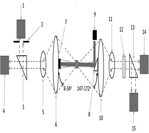
[0028] Such as figure 2As shown, the polarized cloud particle detector capable of distinguishing cloud particle phase states of the present invention includes a laser emitting module, a forward laser receiving module, a backward laser receiving module, a photoelectric detection module, a data acquisition module and a system control module. The laser emitting module of the present invention adopts a laser emitter 9, and the laser emitter 9 adopts a single-mode diode laser, and the output wavelength is a single-mode laser with a wavelength of 685nm (the diameter of the laser spot is 2mm, and the power is 50mw). Straight back, shoot towards cloud particles. The forward laser receiving module includes an optical trap 7, a front and rear scattered light collecting lens 6, a front and rear scattered light collimator mirror 5, a front and rear scattered light beam splitting prism 3, and a circular aperture diaphragm 2; the backward laser receiving module includes a total reflection ...


PUM

PropertyMeasurementUnit
emission peakaaaaaaaaaa

Abstract

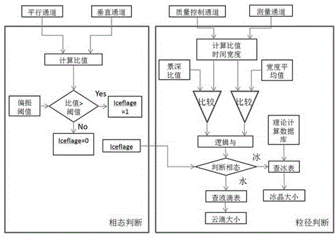
The present invention discloses a cloud particle detection method and a cloud particle detector. According to the cloud particle detection method, the backscattering signals of the cloud particles are received to detect the depolarization condition of the cloud particles on laser so as to obtain the phase state of the cloud particles; and the forward scattering signals of the cloud particles are received to detect the equivalent optical particle size of the cloud particles. According to the present invention, with the cloud particle detection method and the cloud particle detector, the small ice crystal (less than 50 [mu]m) in the mixing phase state cloud can be effectively detected.

Description

technical field [0001] The invention relates to a cloud particle detection method and a detector capable of distinguishing cloud particle phase states. Background technique [0002] The size spectrum information of small ice crystals in clouds plays an important role in the scientific research of cloud radiology and cloud physics. Clouds cover about 60%-70% of the Earth's surface, and the global average net radiative forcing from clouds is about four times greater than the possible greenhouse effect caused by increased carbon dioxide. Among many types of clouds, cold clouds have a particularly important impact on the Earth's radiation budget. The IPCC Fourth Assessment Report pointed out that there are still great uncertainties in the role of clouds in radiative forcing and climate change, and one of the most important sources of uncertainty is caused by cold cloud radiation. The radiation characteristics of cold clouds are not only determined by the ice water content, but...

Claims


Application Information

Patent Timeline
Patent Type & Authority Applications(China)
IPC IPC(8): G01N15/00G01N15/02
Inventor 卜令兵朱浩黄兴友郜海洋
Owner NANJING UNIV OF INFORMATION SCI & TECH
Learn More