
All-optical interconnection data center network system based on software defined network and data communication method

A technology of data center network and software-defined network, which is applied in the direction of digital transmission system, transmission system, data exchange network, etc., and can solve the problem of reduced configuration time, optical circuit switching delay performance, high energy consumption, and limited network Scalability and other issues, to achieve the effect of breaking through bandwidth and rate bottlenecks, eliminating energy consumption, and high communication requirements

Active Publication Date: 2015-12-16
CHONGQING UNIV
View PDF3 Cites 28 Cited by
  • Summary
  • Abstract
  • Description
  • Claims
  • Application Information

AI Technical Summary

Problems solved by technology

The traditional network is relatively simple, but there are also many problems: high energy consumption, complex links, high delay, and the core switch at the top of the tree structure is likely to become a bandwidth bottleneck and limit the scalability of the network
Optical circuit switching is usually based on micro-electromechanical systems (MEMS). The long configuration time of MEMS leads to a decrease in the delay performance of optical circuit switching. However, for long-term and high-traffic communications, optical circuit switching can provide high-bandwidth switching paths.
However, for bursty small traffic, its performance will be significantly reduced
Although the optical interconnection DCN architecture has the advantages of high bandwidth and low latency, the problem of high energy consumption has not been well resolved. With the continuous expansion of the DCN network scale, its energy consumption problem has become increasingly prominent. One of the challenges for the normal operation of DCN

Method used


Image

  • All-optical interconnection data center network system based on software defined network and data communication method
  • All-optical interconnection data center network system based on software defined network and data communication method
  • All-optical interconnection data center network system based on software defined network and data communication method

Examples


Embodiment 1

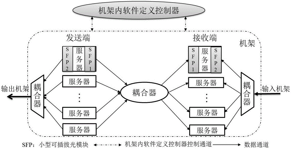
[0074] Such as Figure 9 As shown, server A sends data to server B. The software-defined controller in the rack first analyzes the characteristics of the data traffic, determines that the traffic is communication traffic in the rack, marks the traffic and caches it in the corresponding queue. The controller runs a software-defined bandwidth resource allocation algorithm, and polls the servers in the rack according to the "time information table". When server A is polled, the controller sends a "token" to server A, and the "token" informs Server A has the sending authority, and server A starts sending data after confirming the "token" to the controller. Server A encapsulates the information to be sent. The encapsulated information includes the address information of the active server A and the address information of the destination server B. The encapsulated information is modulated onto the optical carrier λ1 and sent to the machine through the coupler module in broadcast mod...

Embodiment 2

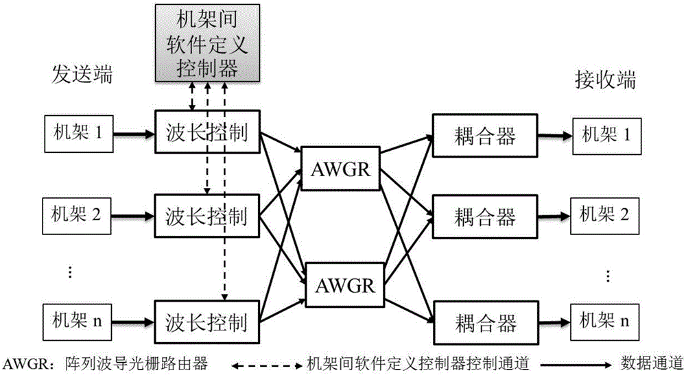
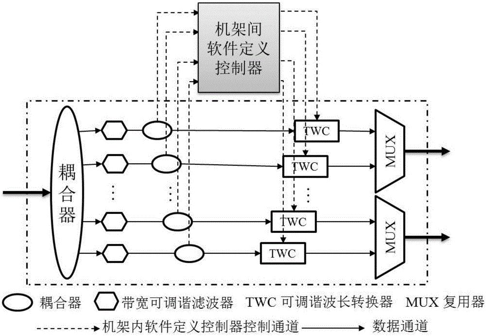
[0076] Such as Figure 10 As shown, server C in rack 1 sends a connection request to server D in rack 2 . Server C generates a data stream, which is analyzed by the controller in the rack. The data stream is out-of-rack traffic, which is marked and cached in the corresponding queue. For the data outside the rack, the data transmission does not need to follow the bandwidth resource allocation principle, and the data is directly transmitted. First, server C encapsulates the information to be sent. The encapsulated information includes the address information of active rack 1 and source server C, and the address information of destination rack 2 and destination server D. Secondly, the SFP optical module The signal is modulated onto the optical carrier and sent to the optical Clos network connecting each rack through the coupler. The wavelength λ1 output from rack 1 is forwarded to the input module wavelength control module of the optical Clos network. The wavelength input contr...


PUM


Abstract

The invention relates to an all-optical interconnection data center network system based on a software-defined network and a data communication method, and relates to the technical field of cloud computing and communication. A passive optical network interconnection server constructed rack of the system replaces a traditional top-of-rack switch. An optical Clos network interconnects the racks to construct an all-optical interconnection data center network. An in-rack passive optical network is composed of a coupler module. The optical Clos network is composed of a wavelength control module, an array waveguide grating router, and a coupler. In-rack software defined controllers and inter-rack software defined controllers are interconnected in a hierarchical structure, and respectively control data communication of in-rack servers and inter-rack servers in a centralized mode so as to separate control and forwarding. The all-optical interconnection data center network system of the invention is highly energy-saving and cost-effective, and can improve the management efficiency and network performance of the data center network.

Description

technical field [0001] The invention belongs to the technical field of cloud computing and communication, and relates to a software-defined all-optical interconnection data center network system and a data communication method. Background technique [0002] Cloud computing is a computing model that uses the Internet to access shared resource pools (such as servers, network resources, storage devices, applications, etc.) anytime, anywhere, on demand, and conveniently. Data Center is the core platform and infrastructure for cloud computing to realize centralized processing, storage, transmission, exchange and management of information. Data Center Network (DCN) is a network that interconnects large-scale (tens of thousands or even hundreds of thousands) of servers in the data center to realize large-scale distributed computing, and is used for the transmission and exchange of large amounts of data between servers in the data center. As the infrastructure of cloud computing an...

Claims


Application Information

Patent Timeline
IPC IPC(8): H04L12/851H04L12/863H04Q11/00
CPCH04L47/24H04L47/50H04Q11/0005
Inventor 蔡岳平周丽罗森
Owner CHONGQING UNIV
Learn More