Desulfurization wastewater pre-evaporation zero discharge treatment apparatus

A technology for desulfurization wastewater and treatment equipment, which is applied in water/sewage treatment, water/sludge/sewage treatment, and the use of liquid separation agents, etc., which can solve problems such as high operating costs, high equipment costs, and strict environmental protection requirements, and achieve extended Effect of residence time, reduction of operation risk and reduction of equipment investment

Inactive Publication Date: 2015-12-23
江苏中顺节能科技有限公司
View PDF4 Cites 15 Cited by
  • Summary
  • Abstract
  • Description
  • Claims
  • Application Information

AI Technical Summary

Problems solved by technology

The use of chemical dosing to treat wastewater has been unable to meet the economic benefits and increasingly stringent environmental protection requirements of coal-fired boiler users
At present, there are zero-discharge solutions for desulfurization wastewater from different processes in China, including evaporation crystallization, deep extraction, etc., but they cannot be popularized because of the high cost of equipment and high operating costs.
The desulfurization wastewater is sprayed into the flue between the air preheater and the electrostatic precipitator by using an atomizing nozzle, and the flue evaporation technology that evaporates the wastewater through high-temperature flue gas to form solid particles and is removed by the dust collector can better treat the desulfurization wastewater , but in this process, if the desulfurization wastewater is not completely evaporated in the flue, the residual desulfurization wastewater droplets will directly enter the electrost

Method used


Image

  • Desulfurization wastewater pre-evaporation zero discharge treatment apparatus
  • Desulfurization wastewater pre-evaporation zero discharge treatment apparatus
  • Desulfurization wastewater pre-evaporation zero discharge treatment apparatus

Examples


Embodiment Construction

[0018] The preferred technical solutions of the present invention will be described in detail below in conjunction with the accompanying drawings.

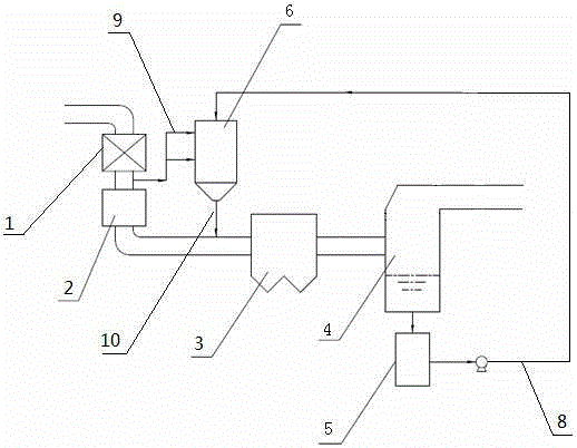
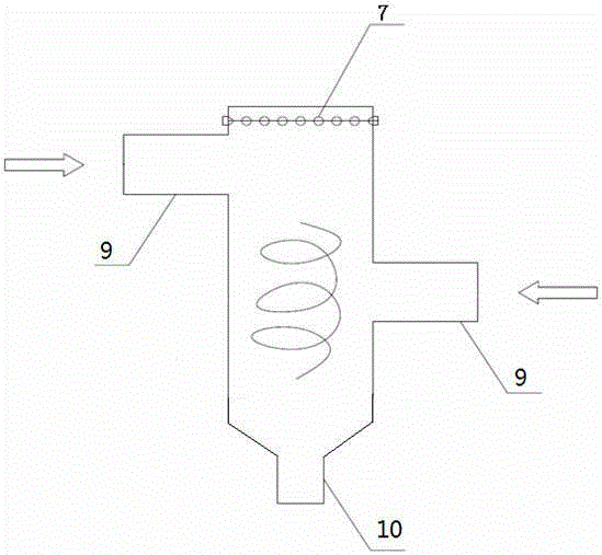
[0019] As shown in the figure, a pre-evaporation and zero-emission treatment device for desulfurization wastewater includes a denitrification device 1, an air preheater 2, a dust collector 3 and a desulfurization tower 4 connected in sequence by pipelines; the denitrification device 1 is connected to the mechanical equipment. On the waste heat flue gas discharge pipe, the desulfurization tower 4 has a spray layer for purifying the flue gas. The spray layer sprays desulfurization slurry, and the desulfurization slurry sprays and contacts the flue gas entering the desulfurization tower 4. The upper part of the layer also has a purified gas discharge pipeline, which is located in the desulfurization tower 4 and is connected to the waste water tank 5. The gypsum slurry discharged from the desulfurization tower 4 passes through the dehy...


PUM


Abstract

The present invention discloses a desulfurization wastewater pre-evaporation zero discharge treatment apparatus, which comprises a denitration device, an air preheater, a dust remover and a desulfurization tower, wherein the denitration device the air preheater, the dust remover and the desulfurization tower are sequentially communicated through pipelines, the desulfurization tower is communicated to a wastewater box, the wastewater box is provided with an evaporator, an atomization nozzle is arranged inside the evaporator, the wastewater box and the evaporator are communicated through a wastewater pipeline, the evaporator is respectively provided with a gas pipeline and a wet gas pipeline, the gas pipeline is connected to the pipeline between the denitration device and the air preheater, and the wet gas pipeline is connected to the pipeline between the air preheater and the dust remover. Compared with the apparatus in the prior art, the apparatus of the present invention has the following characteristic that the high temperature gas flow is introduced to enhance the heat exchange between the high temperature gas flow and the desulfurization wastewater, such that the complete evaporation of the desulfurization wastewater during the being discharged out of the evaporator is achieved, the solid particles in the wastewater are re-collected after being dried, and the desulfurization wastewater zero discharge effect is achieved.

Description

technical field [0001] The invention belongs to the field of flue gas desulfurization wastewater treatment, and in particular relates to a pre-evaporation zero-emission treatment device for desulfurization wastewater. Background technique [0002] Limestone-gypsum wet desulfurization technology is currently the most widely used flue gas desulfurization technology in thermal power plants. During the operation of the desulfurization device, a large amount of wastewater is regularly discharged, that is, desulfurization wastewater. The wastewater has the characteristics of high concentration of suspended solids, high concentration of inorganic salts and heavy metal ions, and is often treated by traditional chemical treatment methods of neutralization, precipitation, flocculation, concentration and clarification, but the chlorine ions in the treated water cannot be removed, and it is difficult to enter the system for recycling At the same time, this method also has many disadvan...

Claims


Application Information

Patent Timeline
IPC IPC(8): C02F1/16B01D47/06
Inventor 代旭东葛传芹曲守信刘宏范玺
Owner 江苏中顺节能科技有限公司
Why Eureka
Try Eureka