Glass furnace flue gas desulfurization and denitrification system and process

A glass furnace, desulfurization and denitrification technology, applied in the direction of air quality improvement, dispersed particle separation, chemical instruments and methods, etc., can solve the problems of poor denitrification effect, large ammonia consumption, and external supply of ammonia source

Active Publication Date: 2015-12-30
SHENWU TECH GRP CO LTD
View PDF7 Cites 7 Cited by
  • Summary
  • Abstract
  • Description
  • Claims
  • Application Information

AI Technical Summary

Problems solved by technology

Therefore, the present invention does not need external ammonia supply for the primary denitrification process, and the remaining NOx in the flue gas is removed twice in the subsequent ammonia desulfurization process, which solves the problem th

Method used


Image

  • Glass furnace flue gas desulfurization and denitrification system and process

Examples


Embodiment 1

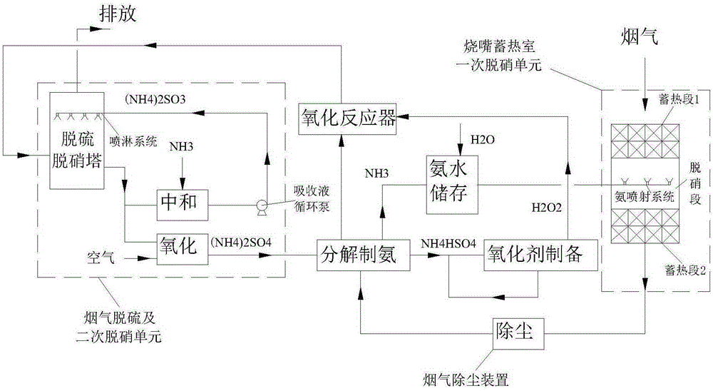
[0056] The invention provides a glass furnace flue gas desulfurization and denitrification system and process. The system includes a glass furnace burner regenerator primary denitrification unit, a flue gas dust removal device, a decomposition ammonia device, an oxidant preparation device and a flue gas desulfurization device. and secondary denitrification unit.

[0057] Among them, the flue gas passes through the primary denitrification unit of the regenerator of the burner of the glass furnace, the flue gas dust removal device, the decomposition ammonia device, and the flue gas desulfurization and secondary denitrification unit.

[0058] The primary denitrification unit of the burner regenerator of the glass furnace includes the first heat storage section, the denitration section and the second heat storage section. The denitration section is set between the first heat storage section and the second heat storage section. Ammonia injection system, the ammonia water storage de...

Embodiment 2

[0079] The same desulfurization and denitrification system and process as in Example 1 were used. When the flue gas temperature in the regenerator chamber of the glass furnace burner drops to 1100°C, denitrification will be performed once, and the temperature of the flue gas leaving the glass furnace will be ˉ280°C. After electrostatic precipitation, the temperature of the flue gas is 240°C, and it enters the ammonium sulfate decomposition ammonia production device. The flue gas exchanges heat with the desulfurization product ammonium sulfate solution, and the flue gas cooled to 150°C is mixed with the prepared oxidant hydrogen peroxide to make the hydrogen peroxide and the flue gas The molar ratio of NO is 1.35, and the NO in the flue gas is oxidized to NO 2 , and then enter the desulfurization and denitrification tower. The pH value of the desulfurization absorption liquid is maintained at about 6, and the desulfurization and secondary denitrification processes are complete...


PUM


Abstract

The invention discloses a glass furnace flue gas desulfurization and denitrification system and process. The system comprises a glass furnace burner regenerative chamber primary denitrification unit, a flue gas dust removal device, a decomposition-process ammonia production device and a flue gas desulfurization and secondary denitrification unit. Primary denitrification of flue gas is completed in a glass furnace burner regenerative chamber by using ammonia as a denitrification agent, secondary denitrification can be realized during subsequent ammonia desulfurization, ammonia and ammonium hydrogen sulfate are produced by using a desulfurization product ammonium sulfate, the ammonia can be used as a primary denitrification absorbent, hydrogen peroxide is further produced by using the ammonium hydrogen sulfate and is used as an oxidant of NOx in the flue gas, residual liquid can be cyclically utilized, thereby the ammonia does not need to be externally supplied during the primary denitrification in the invention, and the secondary removal of the remaining NOx in the flue gas is realized in the subsequent ammonia desulfurization process. The glass furnace flue gas desulfurization and denitrification system and process disclosed by the invention are simple and the desulfurization and denitrification efficiency are high.

Description

technical field [0001] The invention relates to a glass kiln flue gas desulfurization and denitrification system and process. Background technique [0002] The main pollutants in glass furnace flue gas are SOx, NOx and dust, among which SOx is mainly SO 2 , NOx pollutants are mainly NO and NO 2 , the dust particles in the flue gas are fine and sticky. Since the glass industry started late in the control of flue gas emissions, some flue gas from glass furnaces is even discharged directly into the atmosphere without treatment, causing increasingly serious pollution to the atmosphere. With the improvement of environmental protection requirements, the glass industry is urged to carry out comprehensive treatment of desulfurization, denitrification and dust removal of glass furnace flue gas. [0003] At present, flue gas denitrification technology uses denitrification reducing agent to react with NOx in flue gas for denitrification. When ammonia water is used as the denitrific...

Claims


Application Information

Patent Timeline
IPC IPC(8): B01D53/75B01D53/60B01D53/96
CPCY02A50/20
Inventor 窦从从吴道洪
Owner SHENWU TECH GRP CO LTD
Why Eureka
Try Eureka