Capacitor and permanent magnetic direct-current motor
A capacitor and capacitor ceramic technology, applied in the direction of fixed capacitor dielectric, fixed capacitor terminal, fixed capacitor components, etc., can solve the problems of complex installation and welding process, large capacitor footprint, etc., to achieve small size, prolong life, The effect of suppressing sparks
- Summary
- Abstract
- Description
- Claims
- Application Information
AI Technical Summary
Problems solved by technology
Method used
Image
Examples
no. 3 Embodiment
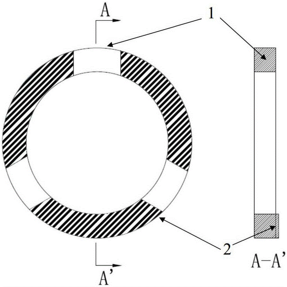
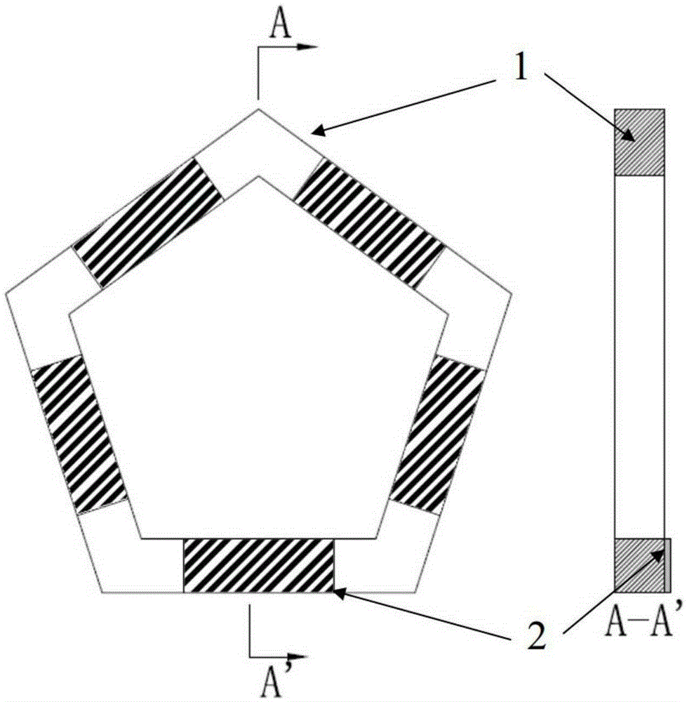
[0041] refer to image 3 , The third specific embodiment of the capacitor of the present invention, the capacitor is a regular pentagon, the capacitor ceramic substrate 1 is connected with five end electrodes 2, the cross section of the capacitor substrate 1 is rectangular, and the end electrodes 2 are distributed on one end surface.
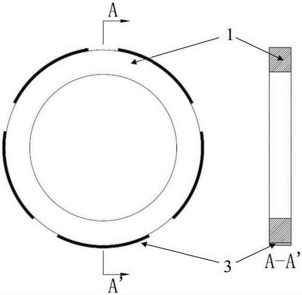
[0042] refer to Figure 4 , the fourth specific embodiment of the capacitor of the present invention, the capacitor is ring-shaped, including a capacitor ceramic substrate 1, three positive end electrodes 2, outer side electrodes 3 and inner side electrodes 3', each electrode middle electrode, inner and outer side electrodes The electrodes are connected to each other, and the cross section of the capacitor substrate 1 is rectangular.
[0043] refer to Figure 5 and Figure 6 , the fifth specific embodiment of the capacitor of the present invention, the capacitor is ring-shaped, comprising a capacitive ceramic substrate 1, three positive end ele...
no. 1 Embodiment
[0045] refer to Figure 7 , the first specific embodiment of a permanent magnet DC motor of the present invention, the rotor of the motor is loaded with an annular capacitor I, and the rotor of the motor includes a rotating shaft 4, three sets of coils 8, three iron chips 9, an adjusting gasket 5, a copper ring 6, Insulating bushing 7, commutator 11 and oil stop gasket 12. The ring capacitor I penetrates into the rotating shaft 4 and then is inserted into the commutator 11 . The installation method of the ring capacitor I on the rotor is as follows: the installation direction of the ring capacitor I is that the end electrode of the ring capacitor is facing the coil 8 and the iron core 9, and the two taps 13 of the two adjacent coils 8 and the protruding part 14 from the commutator skeleton A piece of copper protruding from the middle is welded on the electrode 2 of the ring capacitor I, so as to realize the electrical connection of the ring capacitor I, the coil 8 and the com...
no. 2 Embodiment
[0064] Further as a preferred embodiment, the second specific embodiment of the components of the capacitor ceramic substrate and the preparation method is as follows: first ball milling and mixing SrCO 3 and TiO 2 , where SrCO 3 The amount of substance with TiO 2 The molar ratio of the substance is 1.0; after mixing and drying, the solid-phase synthesis powder is obtained at 1000°C-1300°C to obtain SrTiO 3 Powder;
[0065] In SrTiO 3 Add semiconducting agent Nb to the powder 2 o 5 , La 2 o 3 、 Ta 2 o 5 One or more of them, while adding the additive MnCO 3 , SiO 2 、Na 2 CO 3 , Li 2 CO 3 One or more of , CuO, etc.;
[0066] The content of the semiconducting agent is 0.1% to 8% of the amount of the synthetic powder material, and the total amount of the remaining additives is 0.3% to 5% of the amount of the synthetic powder material;
[0067] Press the prepared and mixed ceramic material into a strontium barium calcium titanate ceramic blank;
[0068] Debinding ...
PUM
| Property | Measurement | Unit |
|---|---|---|
| Capacitance | aaaaa | aaaaa |
Abstract
Description
Claims
Application Information
 - R&D
- Intellectual Property
- Life Sciences
- Materials
- Tech Scout
- Unparalleled Data Quality
- Higher Quality Content
- 60% Fewer Hallucinations
Browse by: Latest US Patents, China's latest patents, Technical Efficacy Thesaurus, Application Domain, Technology Topic, Popular Technical Reports.
© 2025 PatSnap. All rights reserved.Legal|Privacy policy|Modern Slavery Act Transparency Statement|Sitemap|About US| Contact US: help@patsnap.com


