
Flashing optical fiber panel and preparation method

A scintillation fiber and panel technology, applied in optics, photographic technology, X-ray/infrared technology, etc., can solve the problems of difficult to enlarge the size of photomultiplier tube and CCD device, low resolution, slow crystal growth, etc., to overcome the detection Efficiency and resolution restrict each other, high energy resolution, and fast response.

Active Publication Date: 2016-02-03
CHINA BUILDING MATERIALS ACAD
View PDF3 Cites 10 Cited by
  • Summary
  • Abstract
  • Description
  • Claims
  • Application Information

AI Technical Summary

Problems solved by technology

[0004] At present, the materials suitable for X-ray imaging mainly include scintillation crystals and directional growth of CsI crystals on fiber optic panels, but scintillation crystals are difficult to prepare, expensive, slow crystal growth, crystal anisotropy, and activators exist in the crystals. The segregation phenomenon makes the luminescent performance of each part different, the production of large quantities and large sizes is difficult, the utilization rate of the crystal is not high, and the detection efficiency is low, which limits its application to a large extent; while in the optical fiber The method of directional growth of CsI crystal in the panel, due to the small thickness of the CsI crystal film, leads to low resolution, and increasing the film thickness will reduce the detection efficiency, which also greatly limits the application, and the scintillation crystal and optical fiber The method of directional growth of CsI crystals in the panel is mainly used in the field of soft X-rays with energy 100keV ~ 150keV. For hard X-rays and γ-rays with energy ≥ 400keV, due to the strong penetrating ability of high-energy rays and a large amount of radiation, scintillator materials cannot These high-energy radiation will reduce the transmittance of the optical fiber, or even make it opaque, resulting in the failure of the detection system or low detection efficiency. At the same time, these radiations will also damage the measurement system at the back end of the system such as photomultiplier tubes and CCD devices. On the other hand, the size of the photomultiplier tube and CCD device is difficult to increase. After the size is increased, it can only detect whether there are X-rays, γ-rays, etc., and the radiation intensity in the target area, and the imaging quality will deteriorate and the resolution will decrease. , but it is not applicable to the detection of the ray field distribution of the target, the imaging detection of the ray source and the precise imaging.

Method used

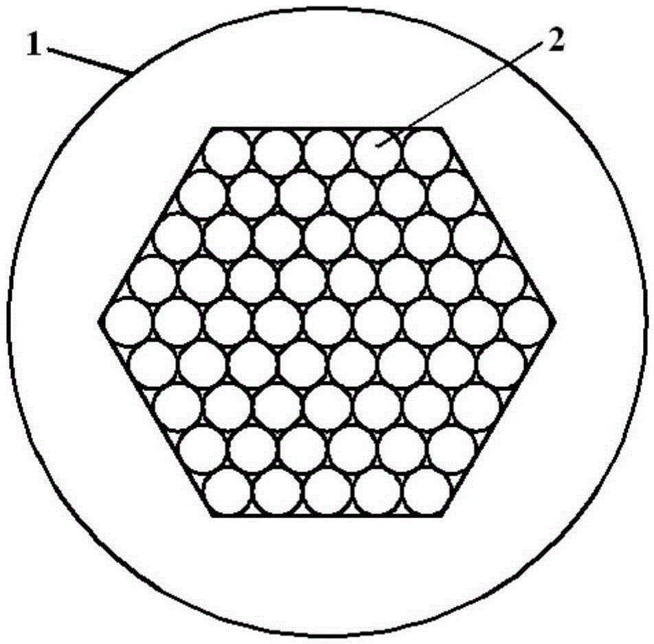

Image

  • Flashing optical fiber panel and preparation method
  • Flashing optical fiber panel and preparation method
  • Flashing optical fiber panel and preparation method

Examples


preparation example Construction

[0048] A kind of preparation method of flashing optical fiber panel provided by the present invention comprises the following steps:

[0049] ①Preparation of glass batch materials: Weigh each raw material according to the raw material components, mix and grind all raw materials evenly to obtain batch materials;

[0050] ② Melting of glass batch materials: Mix the above prepared glass batch materials evenly, put them into platinum crucibles, and place them in a glass melting furnace under a reducing atmosphere for melting. The glass melted under reducing atmosphere conditions can effectively improve The flickering luminous efficiency of the glass and the reduction atmosphere are obtained by directly passing the mixed gas of nitrogen and hydrogen into the crucible with the batch material, the melting temperature is 1400-1500 ℃, and the temperature is kept for 6-9 hours after melting. Perform manual stirring 3 times to improve the melting quality and clarification quality of the ...

Embodiment 1

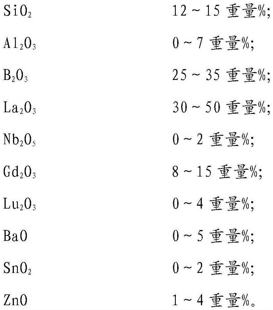
[0064] First, select the raw materials according to the glass composition of Example 1 in Table 1, so that the ingredients meet the chemical composition of the glass in Table 1. After thorough mixing and grinding, the glass batch is prepared, and then poured into a platinum crucible, at a temperature of 1450 ° C. Melt in a glass melting furnace in a reducing atmosphere, directly pass the mixed gas of hydrogen and nitrogen into the crucible with batching materials to obtain a reducing atmosphere, heat it for 8 hours after melting, and manually stir the glass liquid 3 times during the heat preservation period. Improve the melting quality and clarification quality of the glass melt. After the glass batch material is melted into a homogeneous glass melt, the glass melt leakage is formed into a glass rod and placed in a muffle furnace at 600°C for annealing treatment. Turn off the electric furnace after one hour, then cool down to room temperature naturally with the furnace cooling,...

Embodiment 2

[0066] Select raw materials according to the glass composition of Example 2 in Table 1, so that the ingredients meet the chemical composition of the glass in Table 1. After thorough mixing and grinding, the glass batch is prepared, then poured into a platinum crucible, and reduced with carbon monoxide at a temperature of 1400 ° C. It is melted in the glass melting furnace in the atmosphere, and the process of obtaining the carbon monoxide gas reducing atmosphere is to place a small crucible with carbon powder or graphite powder in the melting furnace for 2 hours to keep warm. After melting, keep it warm for 9 hours. During the heat preservation period, manually stir the molten glass 3 times to improve the melting quality and clarification quality of the glass melt. After the glass batch material is melted into a homogeneous glass melt, the glass melt leakage is formed into The glass rod is placed in a muffle furnace at 500°C for annealing treatment. After 4 hours of heat preser...


PUM

PropertyMeasurementUnit
Average linear expansion coefficientaaaaaaaaaa
Densityaaaaaaaaaa
Average linear expansion coefficientaaaaaaaaaa

Abstract

The present invention discloses a flashing optical fiber panel and a preparation method, the preparation method comprises the following steps: 1, weighing each raw material according to the raw material composition, uniformly mixing all the raw materials and uniformly grinding to obtain a mixture; 2, pouring the mixture into a crucible, and putting the crucible into a reducing atmosphere glass melting furnace to prepare a glass melt; 3, leaking the glass melt to form a glass rod, placing the glass rod into a 500-700 DEG C muffle furnace for insulation, cooling with the furnace and naturally cooling for annealing; 4, cutting the annealed glass, grinding the surface, polishing, and processing into a sample, namely a flashing glass core rod; and 5, using the flashing glass as a core material for preparing the flashing optical fiber panel, matching the core material with leather material glass to pull into optical fiber, arranging the optical fiber, and molding by hot melt pressing to prepare a flashing optical fiber panel blank, and optically processing the flashing optical fiber panel blank to prepare the desired size flashing optical fiber panel; the flashing optical fiber panel achieves the low radiation dose and high-resolution imaging detection of hard X-rays and other high-energy rays.

Description

technical field [0001] The invention relates to the field of optical fiber panel production, in particular to a scintillation optical fiber panel and a preparation method thereof. Background technique [0002] With the strengthening of human activities in high-energy physics, biomedical technology, space detection, industrial detection, and nuclear detection technology, as well as the rapid development of image enhancement technology, many previously invisible and difficult-to-detect objects or events can be directly observed, especially It is the application of high-energy rays such as X-rays and γ-rays in modern nuclear medical equipment, which requires more in-depth and detailed diagnosis and observation of organisms and human bodies (such as early detection of tumors and cancer cells), so that X-rays, γ-rays, etc. High-energy ray diagnosis and observation have been widely used in information acquisition and transmission systems of various biomedical and industrial key eq...

Claims


Application Information

Patent Timeline
IPC IPC(8): C03C4/12C03C3/068G21K4/00
Inventor 贾金升张磊
Owner CHINA BUILDING MATERIALS ACAD
Learn More