Low-carbon type flue gas backflow type steam boiler low-oxygen combustion system

A technology of steam boiler and low-oxygen combustion, which is applied in the direction of combustion method, steam generation method using heat carrier, indirect carbon dioxide emission reduction, etc. Meet low-carbon environmental protection requirements and other issues, achieve the effect of reducing nitrogen oxides and carbon dioxide, broad prospects for promotion and utilization, and improving energy utilization efficiency

Active Publication Date: 2016-02-17
SOUTH CHINA NORMAL UNIVERSITY
View PDF5 Cites 3 Cited by
  • Summary
  • Abstract
  • Description
  • Claims
  • Application Information

AI Technical Summary

Problems solved by technology

However, this steam boiler flue gas waste heat recovery system has the following disadvantages or deficiencies: (1) The heat exchanger adopts a finned heat transfer tube structure, and the heat exchange efficiency is low; (2) Due to the high oxygen content in the combustion gas, resulting in The content of nitrogen oxides and carbon dioxide in the flue gas is high, which does not meet the requirements of low-carbon environmental protection
However, the gas-saving system of the split-combustion gas-fired steam boiler has the following disadvantages or deficiencies: (1) Although the economizer and the heat pipe heat exchanger are used to utilize the waste heat of the flue gas in the second stage, the structure of the economizer and its relationship with it are not clearly disclosed. The connection relationship of other components of the system; (2) Due to the high oxygen content in the combustion gas, the nitrogen oxides and carbon dioxide content in the flue gas are high, which does not meet the requirements of low-carbon environmental protection

Method used


Image

  • Low-carbon type flue gas backflow type steam boiler low-oxygen combustion system
  • Low-carbon type flue gas backflow type steam boiler low-oxygen combustion system
  • Low-carbon type flue gas backflow type steam boiler low-oxygen combustion system

Examples


Embodiment Construction

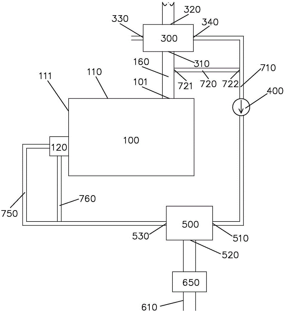
[0035] Please refer to figure 1 According to one embodiment of the present invention, the low-carbon flue gas return steam boiler low-oxygen combustion system of the present invention includes: a steam boiler 100, a burner 120, a flue gas pipeline 160, a first heat exchanger 300 and a mixer 500.

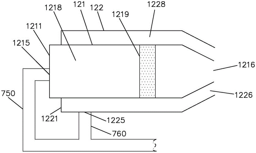
[0036] The steam boiler 100 includes a high-temperature flue gas outlet 101 at the top, and the flue gas pipe 160 communicates with the high-temperature flue gas outlet 101 to discharge the high-temperature flue gas generated in the steam boiler 100 to a chimney (not shown). The burner 120 is arranged on an end wall 111 of the steam boiler 100 , and is used for injecting flame into the combustion chamber of the steam boiler 100 to burn and release heat.

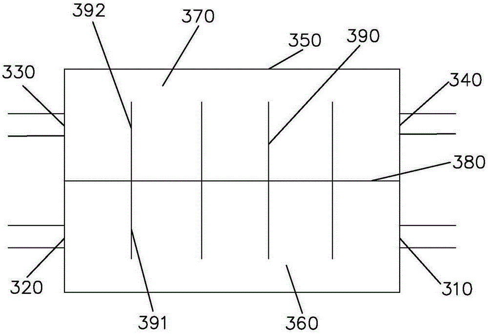
[0037] The first heat exchanger 300 is arranged in the flue gas pipe 160 to heat the air by using the waste heat of the flue gas, and the preheated air is delivered to the burner 120 for combustion. Please refer to figure 2 The ...


PUM


Abstract

The invention discloses a low-carbon type flue gas backflow type steam boiler low-oxygen combustion system which comprises a steam boiler, a combustor and a flue gas pipeline. The combustor is used for jetting flames into the steam boiler for combustion heat emitting, and a high-temperature flue gas outlet in the steam boiler is connected to a chimney through the flue gas pipeline. The system further comprises a first heat exchanger, a gas conveying pipeline and a flue gas backflow branch pipe. The first heat exchanger is arranged in the flue gas pipeline and comprises a flue gas flow path and an air flow path. Air flowing through the air flow path of the first heat exchanger and high-temperature flue gas flowing through the flue gas flow path are subjected to heat exchange and then conveyed to the combustor through the gas conveying pipeline to support combustion. The inlet end of the flue gas backflow branch pipe is communicated with the flue gas pipeline at the part between the high-temperature flue gas outlet and the first heat exchanger, and the outlet end of the flue gas backflow branch pipe is communicated with the gas conveying pipeline to enable part of flue gas and preheated air in the flue gas pipeline to flow back to the combustor together to support combustion.

Description

technical field [0001] The invention relates to boiler equipment, in particular to a steam boiler combustion system. Background technique [0002] Steam boiler is a kind of combustion energy supply system widely used at present, which consumes a lot of energy and causes serious pollution. Steam boilers using natural gas as raw material have partially replaced traditional boilers using coal as fuel. However, the energy loss and environmental pollution caused by it are still the focus of research in the industry. Existing research not only focuses on manufacturing research and development The new steam boiler also pays attention to the energy-saving transformation of the existing steam boiler. [0003] For example, Chinese Patent Publication No. 203323157U discloses a steam boiler flue gas waste heat recovery system. The system includes a steam boiler. The flue gas outlet of the steam boiler is provided with a heat exchanger. The board and the partition divide the box into t...

Claims


Application Information

Patent Timeline
Patent Type & Authority Applications(China)
IPC IPC(8): F23L15/00F22B1/18
CPCY02E20/34
Inventor 赵灵智
Owner SOUTH CHINA NORMAL UNIVERSITY
Why Eureka
Try Eureka