A jet arch for continuous fluidized reactor and aerodynamic fluidization reactor

A technology of jet arch and reactor, which is applied in the field of jet arch and fluidization reactor, can solve the problems of insufficient power, clogging of slag discharge holes, burnout of burner, etc., and achieve the effect of full combustion and avoid clogging

Active Publication Date: 2017-09-12
SICHUAN MINGXIN INVESTMENT
View PDF2 Cites 0 Cited by
  • Summary
  • Abstract
  • Description
  • Claims
  • Application Information

AI Technical Summary

Problems solved by technology

[0006] (1) The power of the dynamic wave is insufficient during the combustion process, and it is impossible to lift and suspend raw materials such as phosphate rock, phosphate rock reducing agent and fuel carbon in the reducing or weakly oxidizing atmosphere space;
[0007] (2) The combustion kinetic wave interface is not obvious, and the reduction space and the oxidation space cannot be relatively isolated;
[0008] (3) The molten substance flowing along the furnace wall during the combustion process is likely to cause blockage of the slag discharge hole, and continuous production cannot be realized
[0010] (1) There are 16 burners, which are divided into upper, middle and lower layers. The upper layer of burners is arranged in the oxidation zone, and the oxidation zone is an exothermic reaction, which does not need to be heated again. The burners are arranged in this area. The high temperature of 1650 ℃ can easily burn out the burner and cause waste of fuel;
[0011] (2) The position of the secondary air inlet pipe is unreasonable. The secondary air is used for the oxidation of phosphorus. The secondary air inlet pipe is arranged in the reduction area below the feed port, and it is difficult to form an oxidation area.
However, the invention still has the following defects: First, the reference document 2 needs to rely on continuous feeding of nitrogen to realize fluidization, so that the gas products in the reduction zone can be sent to the oxidation zone, and fluidization cannot be realized through the inherent structural features of the device, and the nitrogen gas access undoubtedly increases the cost
Secondly, in order to separate the reaction gas products P2 and CO generated in the reduction reaction zone from the blown particulate materials, a cyclone separator is specially installed on the top of the reduction zone, which increases the complexity of the device and also increases the cost.
Furthermore, the gas distributor of this patent has a planar structure. If more solid particles are deposited on the gas distributor, the planar gas distributor is difficult to bear its gravity and is prone to breakage, and the slag port is arranged on the gas distributor. Above, the gas distributor with a planar structure is not conducive to the smooth discharge of slag. Moreover, the power passing through the planar gas distributor during the combustion process is insufficient, so it is difficult to lift up the ore in the reduction reaction zone and evenly disperse it in the entire reduction zone, making Most of the incoming ore is deposited in the middle and lower part of the reduction reaction zone, the reduction effect is not ideal, and the incoming ore is easy to cause blockage to the gas distributor, affecting the continuous progress of the reaction
Finally, according to the description of the invention attached figure 2 or 3, the slag outlet is set above the gas distributor, which is not conducive to the smooth discharge of slag, and it is easy to accumulate on the gas distributor

Method used


Image

  • A jet arch for continuous fluidized reactor and aerodynamic fluidization reactor
  • A jet arch for continuous fluidized reactor and aerodynamic fluidization reactor
  • A jet arch for continuous fluidized reactor and aerodynamic fluidization reactor

Examples


Embodiment Construction

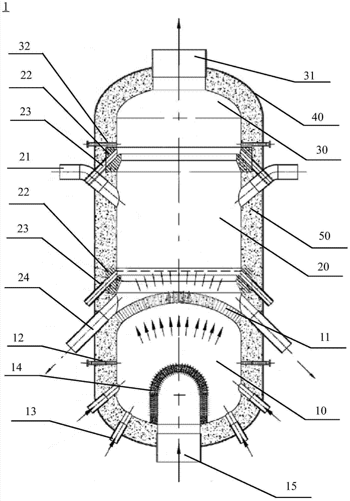
[0041] A detailed description will be given below in conjunction with the accompanying drawings. The jet arch and the gas-generating fluidization reactor involved in the present invention are specifically illustrated by taking the fluidized reactor for preparing phosphorus pentoxide as an example, but it is not intended to limit the present invention, and the jet arch and the gas-generating fluidization reactor of the present invention can also be For the preparation of any other solid fluidized substances, as long as those skilled in the art can think of.

[0042] P of the present invention 2 o 5 The gasification reactor is suitable for the production of phosphoric acid from medium and low-grade phosphate rock. The materials (raw materials) entering the reactor need to go through the refining process in advance. The specific steps of the smelting process are as follows: crush and sieve the collected medium and low-grade phosphate rock (containing 17-22% phosphorus), so tha...


PUM

PropertyMeasurementUnit
diameteraaaaaaaaaa
diameteraaaaaaaaaa

Abstract

The present invention relates to a jet arch and a fluidization reactor for continuous fluidization reactors, characterized in that the jet arch is used to separate the fluidization reactor into two sections for fuel combustion and material reaction respectively. Two chambers are arranged in the fluidized reactor, and the surface of the injection arch is provided with at least one elongated jet channel for injecting the combustion gas from the combustion chamber into the reaction chamber at high speed, The overall distribution of the at least one spray channel on the surface of the spray arch is set in such a way that the injected combustion gas has a high flow rate in the central area and a low flow rate in the peripheral area, so that the high-temperature and high-velocity combustion gas transports the material in a suspended state The lift reacts in the reaction chamber, and after the combustion gas is ejected through the injection arch, the outside air is naturally sucked in from the bottom of the combustion chamber, thereby realizing continuous production. The fluidized reactor of the invention has high gas production efficiency and convenient slag discharge, and can realize a one-step high-efficiency and high-temperature fluidized reaction to directly produce P2O5 from ore and then produce phosphoric acid.

Description

technical field [0001] The invention relates to a jet arch and a fluidization reactor for continuous fluidization reactors. The jet arch and fluidization reactor are especially suitable for high-efficiency high-temperature phosphorus pentoxide generation fluidization reactors, and are also suitable for utilizing fluidization Process and device for preparing phosphoric acid in chemical reactor. Background technique [0002] Phosphoric acid plays an important role in the national economy and is an intermediate raw material for the production of phosphate fertilizers and phosphates. Phosphoric acid and its downstream products are widely used in chemical, agricultural, pharmaceutical, food and electronics industries, and phosphorus pentoxide is the raw material for the production of phosphoric acid. [0003] At present, the production methods of phosphoric acid industry at home and abroad are divided into two process routes: wet method and thermal method. Wet-process phosphoric...

Claims


Application Information

Patent Timeline
Patent Type & Authority Patents(China)
IPC IPC(8): C01B25/12
Inventor 王涛卢成章刘鸿生陈文俊
Owner SICHUAN MINGXIN INVESTMENT
Why Eureka
Try Eureka