A garbage pyrolysis device and method

A pyrolysis and waste technology, applied in special forms of dry distillation, petroleum industry, coke ovens, etc., can solve the problems of being susceptible to seasons, cities, large moisture content of waste, and large fluctuation range, and achieve wide processing capacity adjustment range, group size, etc. The effect of strong adaptability to changes and strong water adaptability

Active Publication Date: 2018-08-14
NORTH CHINA ELECTRIC POWER UNIV (BAODING)
View PDF4 Cites 0 Cited by
  • Summary
  • Abstract
  • Description
  • Claims
  • Application Information

AI Technical Summary

Problems solved by technology

However, most of these pyrolysis devices are difficult to apply to waste raw materials
This is caused by the characteristics of garbage in our country. At present, most of the garbage in our country is original garbage, which has not been sorted, and generally has the following disadvantages: 1. The moisture content of garbage is large and the fluctuation range is large, which is easily affected by weather, seasons, cities, etc. 2. The composition of garbage is extremely complex and fluctuates in a large range, and is easily affected by factors such as seasons and cities; 3. Garbage contains a large amount of polluting elements such as Cl, which is likely to cause secondary pollution during processing; 4 1. The pyrolysis process is an endothermic process, which needs to continuously provide heat to the pyrolysis reactor, which may easily cause excessive energy consumption.

Method used


Image

  • A garbage pyrolysis device and method
  • A garbage pyrolysis device and method
  • A garbage pyrolysis device and method

Examples


Embodiment 1

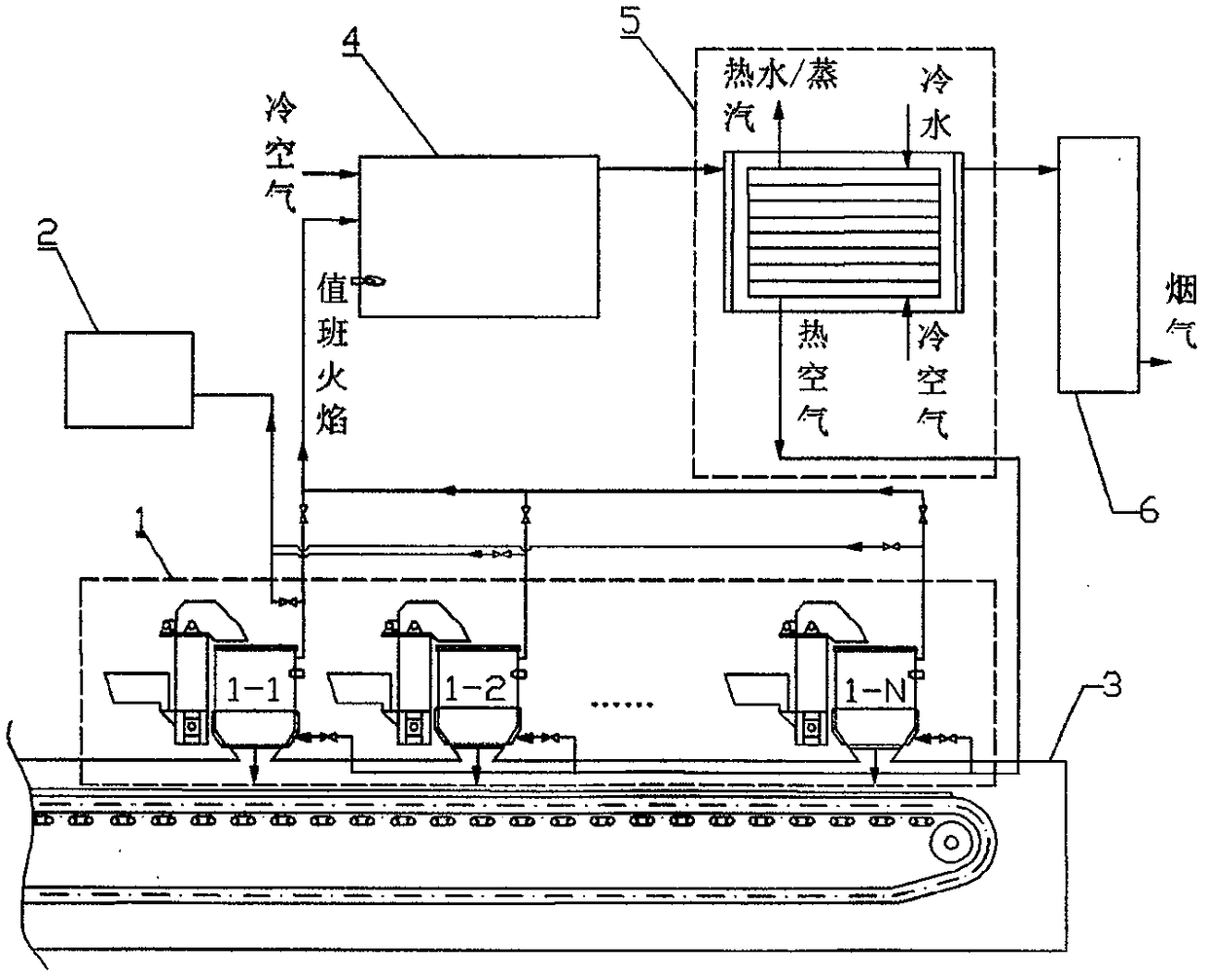
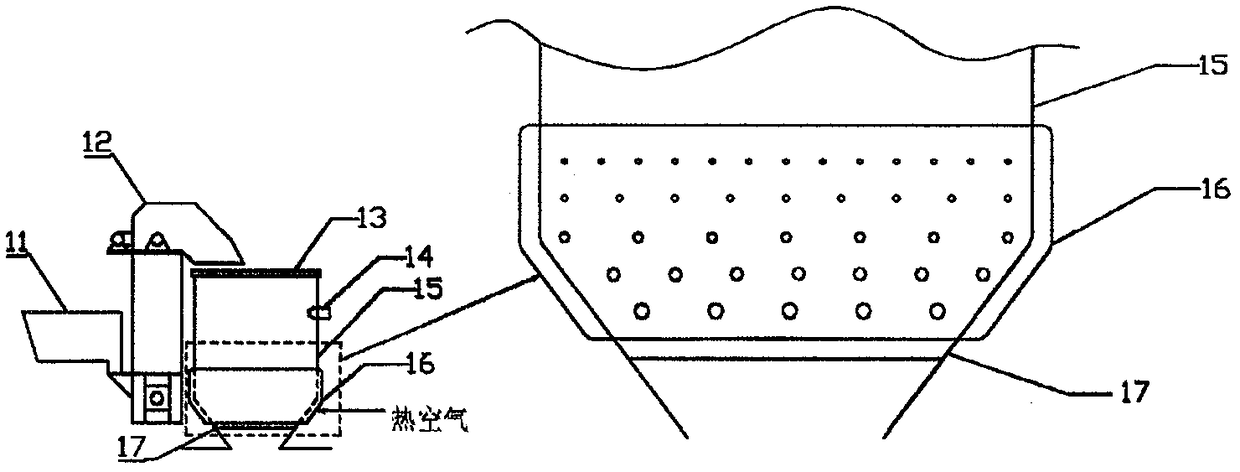
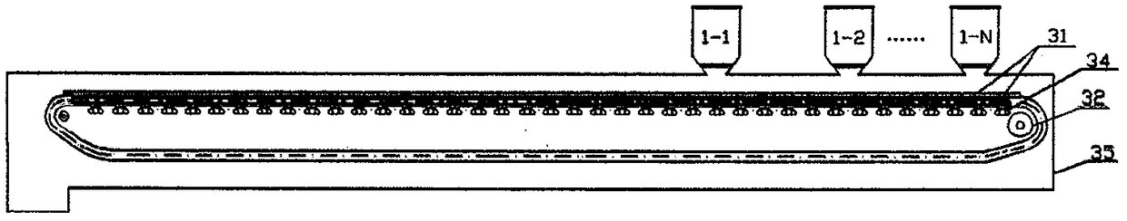
[0046] The garbage pyrolysis system 1 in this embodiment is composed of four parallel fixed-bed pyrolysis reactors, and the above-mentioned devices are used to carry out the harmless treatment of garbage pyrolysis. Garbage enters the pyrolysis reactor through the hopper 11 and the feeding system 12, and the primary feeding amount of each reactor is 3t (moisture content 35%). Among the four fixed-bed pyrolysis reactors, two are in the pyrolysis stage (in the early stage and late stage of pyrolysis respectively), one is in the drying stage, and the other is in the feeding and discharging stage. The hot air temperature at the inlet of the fixed bed pyrolysis reactor is 160°C, and the flow rate in the drying stage is 500Nm 3 / h, the flow rate in the pyrolysis stage is 200Nm 3 / h, no heating air is supplied during the feeding and discharging stages. After the waste is dried in the fixed bed pyrolysis reactor, it is ignited and pyrolyzed. After the pyrolysis is completed, the res...

Embodiment 2

[0048] The garbage pyrolysis system 1 in this embodiment is composed of four parallel fixed-bed pyrolysis reactors, and the above-mentioned devices are used to carry out the harmless treatment of garbage pyrolysis. Garbage enters the pyrolysis reactor through the hopper 11 and the feeding system 12, and the primary feeding amount of each reactor is 3t (moisture content 37%). Among the four fixed-bed pyrolysis reactors, two are in the pyrolysis stage (in the early stage and late stage of pyrolysis respectively), one is in the drying stage, and the other is in the feeding and discharging stages. The hot air temperature at the inlet of the fixed bed pyrolysis reactor is 170°C, and the flow rate in the drying stage is 500Nm 3 / h, the flow rate in the pyrolysis stage is 200Nm 3 / h, no heating air is supplied during the feeding and discharging stages. After the waste is dried in the fixed bed pyrolysis reactor, it is ignited and pyrolyzed. After the pyrolysis is completed, the re...

Embodiment 3

[0050] The garbage pyrolysis system 1 in this embodiment is composed of 8 parallel fixed-bed pyrolysis reactors, and the above-mentioned devices are used to carry out the harmless treatment of garbage pyrolysis. Garbage enters the pyrolysis reactor through the hopper 11 and the feeding system 12, and the primary feeding amount of each reactor is 3.2t (moisture content 35%). Among the 8 fixed-bed pyrolysis reactors, 4 are in the pyrolysis stage (2 are in the early stage of pyrolysis, and 2 are in the late stage of pyrolysis), 2 are in the drying stage, and the other 2 are in the feeding and discharging stages. The hot air temperature at the inlet of the fixed bed pyrolysis reactor is 160°C, and the flow rate in the drying stage is 500Nm 3 / h, the flow rate in the pyrolysis stage is 200Nm 3 / h, no heating air is supplied during the feeding and discharging stages. After the waste is dried in the fixed bed pyrolysis reactor, it is ignited and pyrolyzed. After the pyrolysis is c...


PUM


Abstract

The invention relates to a garbage pyrolyzation device and method. The garbage pyrolyzation device comprises a garbage pyrolyzation system, a water vapor condensation system, a carbon residue collection system, a combustible gas combustion furnace, a garbage heat utilization system and a tail gas treatment system, wherein the garbage pyrolyzation system comprises three groups of fixed bed pyrolyzation reactors which are respectively located in working sections including discharging, feeding, drying, pyrolyzation and the like; after feeding, large quantity of hot air is firstly introduced to finish drying, and water vapor enters the water vapor condensation system; then a proper amount of hot air is introduced to finish pyrolyzation, pyrolyzed gas enters the combustible gas combustion furnace, and carbon residues enter the carbon residue collection system; cold air is heated by virtue of heat of smoke by the garbage heat utilization system, and hot air is used for drying and pyrolyzing the garbage; tail gas enters the tail gas treatment system. By pyrolyzing the garbage by virtue of the garbage pyrolyzation device, the generation and the emission of harmful substances such as dioxin and the like can be effectively avoided, and the innocent treatment of garbage is realized; meanwhile, the garbage is dried and pyrolyzed by virtue of heat generated by the combustion of pyrolyzed gas, so that a self-heating pyrolyzation process of the garbage is basically realized.

Description

technical field [0001] The invention belongs to the field of garbage harmless treatment, and in particular relates to a garbage pyrolysis device and method. Background technique [0002] With the rapid development of the economy and the continuous improvement of people's living standards, the output of municipal solid waste is increasing day by day. The flood of municipal solid waste has become a serious social problem, which not only threatens the safety and survival of the residents themselves, but also brings serious environmental pollution. The harmless and resourceful treatment of domestic waste has become an important issue to be solved urgently by the municipal government. [0003] The composition of municipal solid waste is particularly complex, mainly including kitchen waste, waste paper, waste plastic, waste fabric, vegetation, waste rubber, waste metal, waste glass and ceramic pieces, brick and tile slag, etc. At present, the treatment methods of urban waste are...

Claims


Application Information

Patent Timeline
Patent Type & Authority Patents(China)
IPC IPC(8): C10B53/00
CPCY02P20/129
Inventor 陆强胡斌叶小宁李文涛王昕董长青
Owner NORTH CHINA ELECTRIC POWER UNIV (BAODING)
Why Eureka
Try Eureka