Method for recycling organic matter through organic waste gas adsorption, steam desorption and fractional condensation

A technology of organic waste gas and graded condensation, applied in separation methods, chemical instruments and methods, gas treatment, etc., can solve problems such as pollution, high energy consumption, and high cost of condensate separation, and achieve high recovery purity, no secondary pollution, The effect of low energy consumption

Inactive Publication Date: 2016-04-20
ZHEJIANG UNIV
View PDF5 Cites 34 Cited by
  • Summary
  • Abstract
  • Description
  • Claims
  • Application Information

AI Technical Summary

Problems solved by technology

However, this technology has the disadvantages of high cost of condensate separation and excessive discharge of non-condensable tail gas during operation.
[0003] Chinese invention patent CN104740973A discloses a recovery device for organic solvents in high-concentration organic waste gas, in which the desorbed gas is discharged after condensation and gas-liquid separation, and a small amount of non-condensable organic gas enters the atmosphere, causing pollution
Invention CN103585854A discloses a kind of...

Method used


Image

  • Method for recycling organic matter through organic waste gas adsorption, steam desorption and fractional condensation
  • Method for recycling organic matter through organic waste gas adsorption, steam desorption and fractional condensation

Examples


Embodiment 1

[0035] This embodiment provides an organic waste gas adsorption-steam desorption-staged condensation recovery organic matter device with two adsorbers. The structural diagram is shown in figure 1 . The device includes: 1—exhaust gas inlet; 2—steam inlet; 3—hot air inlet; 4,5—purified gas outlet; 6—cooling air outlet; 7,8—filter cotton; 9,10—adsorber; 11—primary Condenser; 12—oil-water separation device; 13—circulating water pump; 14—circulating water cooling tower; 15—secondary condenser; 16—condensate storage tank; 17—fan; 18—27 are valves.

[0036] The adsorber 9 and the adsorber 10 are filled with honeycomb activated carbon adsorbent.

[0037] The primary condenser 11 is cooled by circulating water; the secondary condenser 15 is refrigerated by vapor compression.

[0038] The filter cotton 7 and the filter cotton 8 can be replaced when the corresponding absorber is in a static state.

[0039] The device is applied to the treatment of exhaust gas in the painting workshop ...

Embodiment 2

[0048] This embodiment provides an organic waste gas adsorption-steam desorption-staged condensation recovery organic matter device with two adsorbers. The structural diagram is shown in figure 1 . The device includes: 1—exhaust gas inlet; 2—steam inlet; 3—hot air inlet; 4,5—purified gas outlet; 6—cooling air outlet; 7,8—filter cotton; 9,10—adsorber; 11—primary Condenser; 12—oil-water separation device; 13—circulating water pump; 14—circulating water cooling tower; 15—secondary condenser; 16—condensate storage tank; 17—fan; 18—26 are valves.

[0049] The adsorber 9 and the adsorber 10 are filled with activated carbon fiber adsorbent.

[0050] The primary condenser 11 adopts circulating water cooling; the secondary condenser 15 adopts absorption refrigeration.

[0051] The filter cotton 7 and the filter cotton 8 can be replaced when the corresponding absorber is in a static state.

[0052] The device is applied to the treatment of dry process waste gas in synthetic leather e...

Embodiment 3

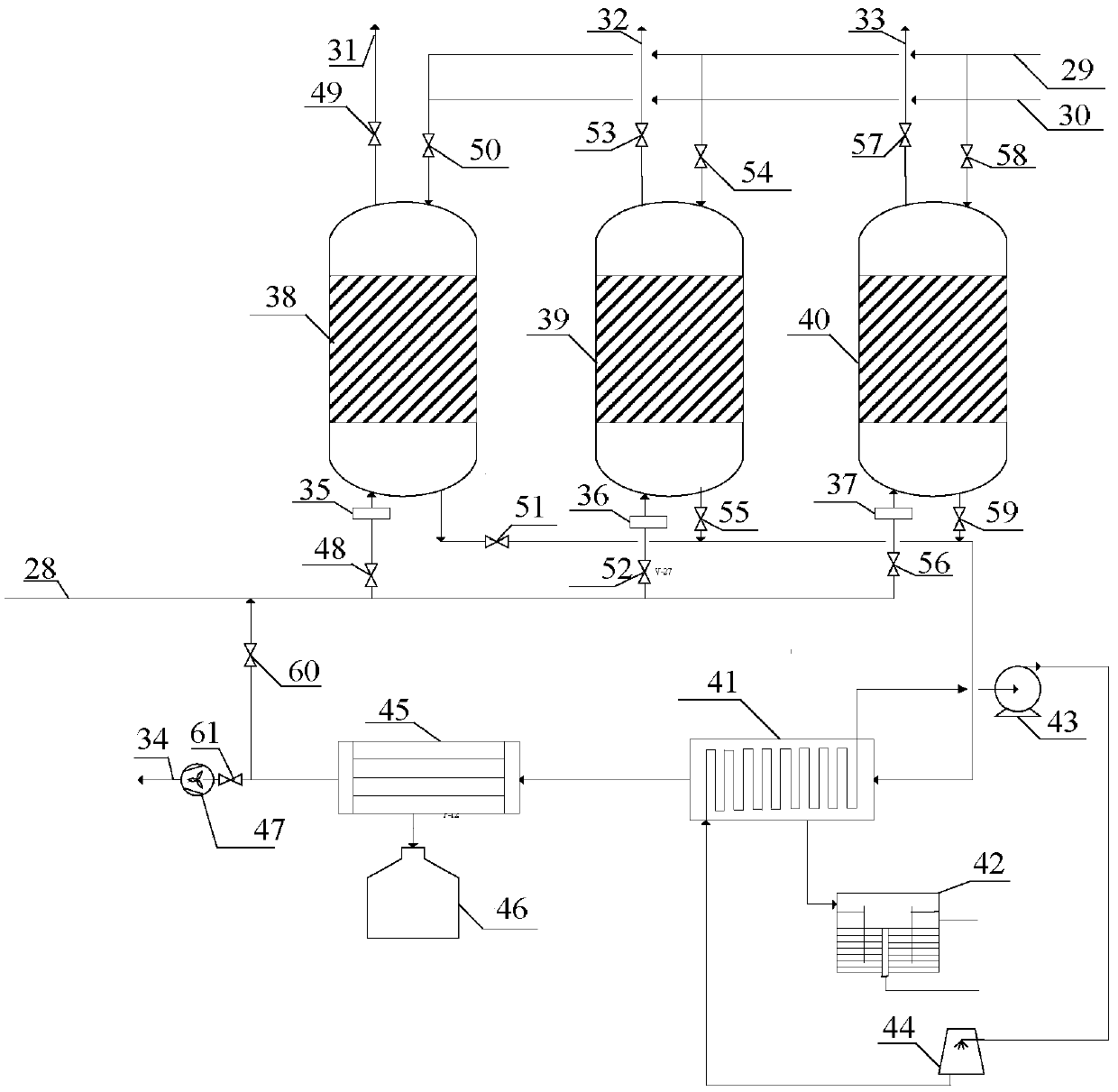
[0061] This embodiment provides an organic waste gas adsorption-steam desorption-staged condensation recovery organic matter device with three adsorbers, the structural diagram is shown in figure 2 . The device includes: 28—exhaust gas inlet; 29—steam inlet; 30—hot air inlet; 31, 32, 33—purified gas outlet; 34—cooling air outlet; 35, 36, 37—filter cotton; 38, 39, 40— Adsorber; 41—primary condenser; 42—oil-water separation device; 43—circulating water pump; 44—circulating water cooling tower; 45—secondary condenser; 46—condensate storage tank; 47—fan; 48—61 is valve .

[0062] The adsorbers 38, 39, 40 are filled with a certain amount of zeolite molecular sieves.

[0063] The primary condenser 41 adopts circulating water cooling; the secondary condenser 45 adopts a semiconductor refrigeration system.

[0064] The filter cottons 35, 36, 37 can be replaced when the corresponding absorbers are in a static state.

[0065] The device is applied to the treatment of exhaust gas in...


PUM


Abstract

The invention relates to the field of organic waste gas recycling and provides a method for recycling organic matter through organic waste gas adsorption, steam desorption and fractional condensation. The method includes the steps that after gas to be treated is pretreated with filtering cotton, the gas enters an adsorber filled with an adsorbing agent and is used for removing organic matter, and the purified gas is exhausted into the atmosphere; desorption and regeneration of the adsorbing agent includes the steps of steam desorption and regeneration, hot air drying and cold air cooling, and steam and desorbed gas are separated through a two-stage condenser. By means of two-step fractional condensation, high-boiling-point organic matter and low-boiling-point organic matter are separated, and the concentration of the recycled organic matter is increased. A small amount of treated gas which is not condensed is introduced into a gas inlet and mixed with inlet waste gas, secondary adsorption is carried out, and it is guaranteed that no tail gas exceeding standards is exhausted in the whole process. Organic matter recycling purity is high, energy consumption is low, and secondary pollution is avoided.

Description

technical field [0001] The invention relates to the field of organic waste gas recovery, in particular to a method and device for organic waste gas adsorption-steam desorption-gradient condensation recovery of organic matter. Background technique [0002] Volatile organic compounds (VOCs) not only have a serious toxic effect on human health, but also one of the important reasons for the formation of smog. The extensive use of organic solvents in industrial production has led to the generation of organic waste gas, which not only pollutes the environment, but is also a serious waste of resources. At present, the adsorption-steam desorption-condensation recovery technology is widely used in the treatment of organic waste gas due to its advantages of good treatment effect, high safety and recyclable organic matter. However, this technology has the disadvantages of high cost of condensate separation and excessive discharge of non-condensable tail gas during operation. [0003]...

Claims


Application Information

Patent Timeline
IPC IPC(8): B01D53/04B01D53/00
CPCB01D53/04B01D53/002B01D2253/102B01D2253/108B01D2253/202B01D2259/4009
Inventor 赵伟荣陈金胜
Owner ZHEJIANG UNIV
Why Eureka
Try Eureka