A method and system for feeding thin sludge into a kiln

A sludge and cement kiln technology, applied in sludge treatment, separation methods, pyrolysis treatment of sludge, etc., can solve the problems of worsening combustion conditions, drop in cement kiln temperature, increase in operating costs, etc., and reduce nitrogen oxides. Emissions, preventing local temperature drop, ensuring yield and quality effects

Active Publication Date: 2018-01-05
BEIJING BUILDING MATERIALS ACADEMY OF SCI RES
View PDF4 Cites 0 Cited by
  • Summary
  • Abstract
  • Description
  • Claims
  • Application Information

AI Technical Summary

Problems solved by technology

These inventions and creations have been developed and utilized after applying for patents. They have a very obvious effect on the treatment of thick sludge and have considerable economic and social benefits. However, they are not suitable for the treatment of thin sludge.
In order to discharge the water in the thin sludge, it takes a lot of heat energy and takes a long time to dry. Therefore, the disposal efficiency of thin sludge is correspondingly reduced, and the operating cost is greatly increased.
In this case, the thin sludge has to be directly injected into the decomposition furnace of the cement kiln. As a result, due to the low calorific value of the thin sludge, the thin sludge is injected into the decomposition furnace to form a floc structure, which makes the local temperature in the decomposition furnace localized. If it is too low, it will cause the cement kiln temperature to drop and deteriorate the combustion conditions, which will greatly affect the output and quality of clinker
Obviously, this method of directly injecting thin sludge into the decomposition furnace is not advisable, and it is not worth the candle

Method used


Image

  • A method and system for feeding thin sludge into a kiln
  • A method and system for feeding thin sludge into a kiln

Examples


Embodiment Construction

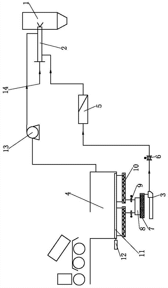
[0066] Such as figure 1 As shown, a method for introducing thin sludge into the kiln provided by this embodiment is to spray the thin sludge into the calciner in the form of mist.

[0067] From figure 1 It can be seen from the figure that the thin sludge is unloaded into the steel structure sludge bin 1 through a truck dedicated to transporting thin sludge, and the inner bottom of the sludge bin 1 is installed with a hydraulic cylinder 12 and a carriage 11 driven by the hydraulic cylinder 12 The broken arch device, through the horizontal reciprocating movement of the broken arch device, pushes the thin sludge to the middle unloading link to avoid bridging phenomenon of the thin sludge in the sludge bin 4, and the thin sludge passes through the bottom of the sludge bin 4 The single screw feeder 10 in the middle is unloaded outside the warehouse. A valve 9 is installed at an orthogonal position below the outlet of the single screw feeder 10, and the thin sludge enters the slud...


PUM


Abstract

The invention discloses a method and a system capable of spraying dilute sludge into a kiln. According to the method, dilute sludge is sprayed into a decomposition furnace in a mist manner, stink produced by the dilute sludge is introduced into the decomposition furnace, and the dilute sludge is subjected to impurity removal before being sprayed. The system comprises the decomposition furnace communicated with a cement kiln, a sludge sprayer is arranged at a feeding port of the decomposition furnace, the feeding port of the sludge sprayer is communicated with a discharging port of a sludge bin through a sludge delivery pump, and a high-pressure air inlet of the sludge sprayer is communicated with a high-pressure air source. The drying process of the dilute sludge is simple, the investment is low, nitrogen oxide emission can be reduced significantly, the drying time is short, the dilute sludge disposal efficiency is high, the floc structure formed by spraying the dilute sludge into the kiln directly is avoided, decrease of the local temperature of the cement kiln and deterioration of the combustion working condition are prevented, and the yield and quality of clinker can be guaranteed. The atomization effect on the dilute sludge is good, the service life of the sludge sprayer can be prolonged, and installation is simple and convenient.

Description

technical field [0001] The invention relates to a method and a system for treating thin sludge by using a cement kiln, in particular to a method and a system for feeding thin sludge into a kiln. Background technique [0002] Sludge is a product produced after wastewater treatment in sewage plants. Sludge can be divided into dry sludge (that is, sludge with very little water content, which is in the form of hard lumps) and wet sludge, and wet sludge can be divided into thick sludge (that is, sludge with high water content, which is in the form of soft lumps). block) and thin sludge (that is, sludge with a very high water content, which is fluid, and its water content can usually reach about 80%). Usually every 10,000 cubic meters of wastewater produces sludge with a water content of about 80%, which can reach 5-10 tons. About 40 million tons of sludge are generated every year. It has seriously affected the development of the city. Conventional sludge disposal methods main...

Claims


Application Information

Patent Timeline
Patent Type & Authority Patents(China)
IPC IPC(8): C04B7/43C04B7/24C02F11/00C02F11/12C02F11/10B01D53/74
CPCB01D53/74B01D2257/90B01D2258/0233C02F11/00C02F11/10C02F11/12C04B7/24C04B7/43Y02P40/10
Inventor 刘海兵顾军王肇嘉陈宁韩立蔡文涛张红玉
Owner BEIJING BUILDING MATERIALS ACADEMY OF SCI RES
Why Eureka
Try Eureka