
A kind of fluidized bed residual oil hydrogenation method

A technology of ebullating bed and bed residue, which is applied in the petroleum industry, refining hydrocarbon oil, etc. It can solve the problems of complicated processing methods and high equipment investment, and achieve the effects of facilitating internal circulation, improving utilization rate, and reducing residual carbon value

Active Publication Date: 2017-04-26
CHINA PETROLEUM & CHEM CORP +1
View PDF5 Cites 0 Cited by
  • Summary
  • Abstract
  • Description
  • Claims
  • Application Information

AI Technical Summary

Problems solved by technology

[0007] The purpose of the present invention is to provide a new ebullated bed residual oil hydrogenation method to overcome the defects of complex processing method and high equipment investment in the existing fluidized bed residual oil hydrogenation method

Method used


Image

  • A kind of fluidized bed residual oil hydrogenation method

Examples


Embodiment 1

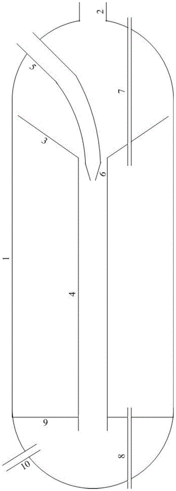
[0037] The raw material residue F1 is an atmospheric residue with high Ca content, and its properties are shown in Table 1. Using a structure such as figure 1 The ebullated bed reactor shown carries out the hydrogenation reaction. Wherein, a diameter-reducing part 6 is provided at the outlet of the high-pressure oil guide pipe 5, and the ratio of the maximum inner diameter to the minimum inner diameter of the diameter-reducing part 6 is 7:1. The largest inner diameter part of the reduced diameter part 6 is located in the vertical oil guide pipe 4, and the ratio of the radial distance between the corresponding outer wall and the inner wall of the vertical oil guide pipe 4 to the inner diameter of the vertical oil guide pipe 4 is 0.2:1. The ratio of the axial distance between the outlet end of the high pressure oil guide pipe 5 and the inlet end of the vertical oil guide pipe 4 to the length of the vertical oil guide pipe 4 is 1:10.

[0038] The ebullating bed hydrogenation ca...

Embodiment 2

[0049] The raw material residue F2 is an atmospheric residue with high Ni and V content, and its properties are shown in Table 4. Using a structure such as figure 1 The ebullated bed reactor shown carries out the hydrogenation reaction. The catalyst is the RDM-33 produced by Sinopec Catalyst Changling Branch developed by the Research Institute of Petrochemical Sciences. The catalyst is made into a cylindrical shape with a diameter of 0.7mm to adapt to the ebullated bed hydrogenation reactor catalyst. 1.5 liters of RDM-33 catalyst was loaded into the ebullating bed hydrogenation reactor, and the height of the catalyst material level was 50% of the height of the ebullating bed reactor.

[0050] Through the high-pressure oil guide pipe 5, feed the residual oil raw material and the hydrogenated vacuum residual oil circulated by the fractionation system into the fluidized bed hydrogenation reactor. The flow rate of the residual oil raw material introduced is 400g / h, and the hydrog...


PUM


Abstract

The invention relates to a boiling bed residue oil hydrogenation method, which comprises that a residue oil raw material enters a boiling bed hydrogenation reactor, hydrogen gas is subjected to a hydrogenation reaction under the effect of a boiling bed hydrogenation catalyst to obtain hydrogenation generation oil, the obtained hydrogenation generation oil is subjected to gas liquid separation in a high-pressure separator, and the liquid phase separated by the high-pressure separator is subjected to fractionation in a fractionation tower to obtain gas, a naphtha distillate, a diesel oil distillate and a hydrogenation normal pressure residue oil. According to the present invention, the poor-quality residue oil raw material can be subjected to the hydrogenation reaction so as to remove most of sulfur, metals and other impurities in the raw material and substantially reduce the residual carbon value, and the obtained hydrogenation normal pressure residue oil can be adopted the catalytic cracking raw material so as to improve the poor-quality raw material oil utilization rate.

Description

technical field [0001] The invention relates to a method for hydrogenation using ebullating bed, more specifically, a method for hydrogenating residual oil in ebullating bed to produce catalytic cracking raw material. Background technique [0002] The efficient utilization and clean processing of heavy oil is becoming a major topic of concern in the global oil refining industry. Coking, solvent deasphalting and other processes have a large number of low-value by-products, which affect the utilization efficiency and economic benefits of residual oil. Hydrogenation of residual oil can simultaneously meet the requirements of efficient utilization of heavy oil and environmental protection. Four process types have been developed for residual oil hydrogenation: fixed bed, ebullating bed, slurry bed and moving bed. Among the four process types, the fixed bed process is mature, easy to operate, and relatively low device investment; hydrogenated residue can be used as RFCC feed. H...

Claims


Application Information

Patent Timeline
Patent Type & Authority Patents(China)
IPC IPC(8): C10G45/16
Inventor 牛传峰邓中活戴立顺聂红邵志才刘涛董凯杨清河胡大为孙淑玲刘学芬
Owner CHINA PETROLEUM & CHEM CORP
Learn More