Three-phase inverter drive method and device employing SPWM control

A technology of a three-phase inverter and a driving method, which is applied in the direction of output power conversion device, conversion of AC power input to DC power output, high-efficiency power electronic conversion, etc. In order to reduce the risk of thermal damage and IGBT gate breakdown, reduce the loss of the drive circuit, and improve the efficiency of the inverter

Inactive Publication Date: 2016-05-04
SHENZHEN ENCOM ELECTRIC TECH
View PDF7 Cites 3 Cited by
  • Summary
  • Abstract
  • Description
  • Claims
  • Application Information

AI Technical Summary

Problems solved by technology

[0004] The existing disadvantage is that when applied to inverter output, the output pulse voltage finally passes through the inductive load to form a continuous approximate sine wave current. During the commutation process, when the current cannot change abruptly in the inductive load, the IGBT Half of the cycle time is always in reverse-phase freewheeling conduction. At this time, the switching state of the drive gate of the IGBT cannot actually control its on or off (because the current will only pass through its antiparallel diode, not Through the conduction channel of the IGBT), such on and off drive pulse signals not only have no effect on the control target at this time, but each drive must consume the power consumption of the drive circuit, and the voltage change of each drive is on the circuit board It may cause coupling and interference to other similar circuits. The charging and discharging process of the insulated gate charge of the IGBT also produces a certain amount of power loss. process, based on the principle that the magnitude of the current is proportional to the strength of the generated electric field, the increase of the current and the interference of the bridge arm or the loop near the peak value will be superimposed on the gate drive signal that is in the freewheeling state, and the degree of interference varies with When the current increases and increases, there may be a risk of IGBT damage when the forward superimposed value is higher than the drive gate withstand voltage. variable circuit design

Method used


Image

  • Three-phase inverter drive method and device employing SPWM control
  • Three-phase inverter drive method and device employing SPWM control
  • Three-phase inverter drive method and device employing SPWM control

Examples


Embodiment Construction

[0032] The principles and features of the present application are described below in conjunction with the accompanying drawings, and the examples given are only used to explain the invention, and are not intended to limit the scope of the present invention.

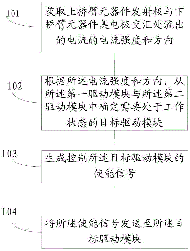
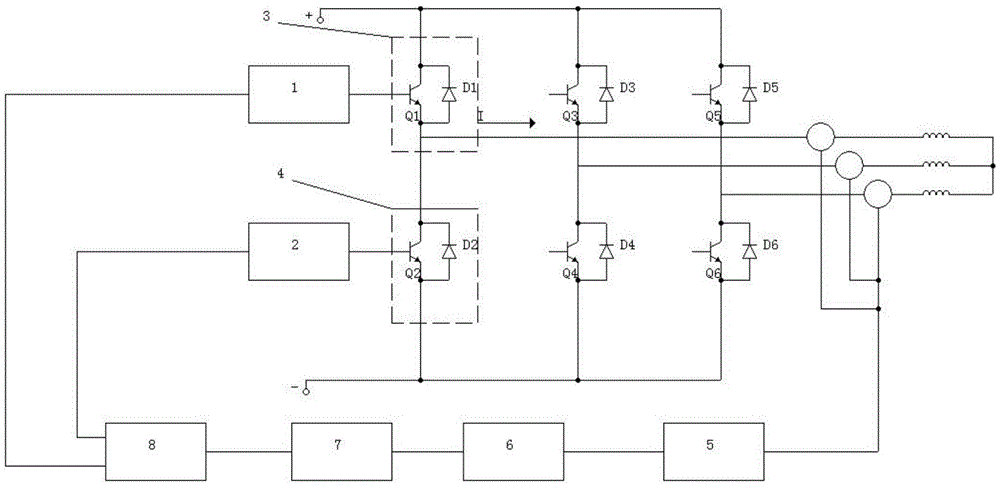
[0033] A three-phase inverter driving method controlled by SPWM is characterized in that, the three-phase inverter specifically includes: an upper bridge arm, a lower bridge arm, a first drive module, and a second drive module; the upper bridge arm The lower bridge arm has the same three-phase semiconductor power switching device, and the upper bridge arm is connected in the same way as the three-phase semiconductor power switching device of the lower bridge arm; the first drive module is connected to the upper bridge arm The control pole of the switching device of the arm is connected, the second drive module is connected with the control pole of the switching device of the lower bridge arm; the emitter of the upper bridg...


PUM


Abstract

The invention discloses a three-phase inverter drive method and device employing SPWM control. The method comprises the following steps: obtaining the current intensity and direction of a current which flows outside from the intersection of an emitter of an upper bridge arm component and a collector of a lower bridge arm component; determining a target drive module to be located in a working state from a first drive module and a second drive module according to the current intensity and direction; generating an enable signal of controlling the target drive module; and transmitting the enable signal to the target drive module, and changing an original all-time uninterrupted work mode into an intermittent work mode. The drive method and device greatly reduce power consumption of switch tubes and drive circuits and avoid the problem that the maximum withstand voltage spike of an IGBT grid is exceeded due to upper bridge and lower bridge-driven intercoupling and positive interference superposition of drive signals caused by electromagnetic radiation generated by the high current.

Description

technical field [0001] The invention relates to an inverter driving method, in particular to an SPWM-controlled three-phase inverter driving method. Background technique [0002] SPWM refers to the sine wave pulse width modulation technology, which is used in the three-phase inverter to regularly modulate the width of the output pulse voltage of the inverter bridge circuit composed of six IGBT switch tubes according to the control algorithm, so that it can be controlled according to the control algorithm. The sine wave changes periodically, so that the DC voltage is converted into an AC voltage whose pulse width changes according to the sine law. When the pulse voltage passes through the motor inductance, it forms a smoother sine wave current, which can drive the motor to run and realize the inverter and frequency conversion of power. . [0003] When the current technical solution is driving the IGBT switch tube, the six-way driving signals are driven by the independent 3 p...

Claims


Application Information

Patent Timeline
Patent Type & Authority Applications(China)
IPC IPC(8): H02M7/5387
CPCH02M7/5387H02M1/0048H02M1/0054Y02B70/10
Inventor 李旭
Owner SHENZHEN ENCOM ELECTRIC TECH
Why Eureka
Try Eureka