Metal contaminating and water thermal aging method for catalytic cracking catalyst

A catalytic cracking and hydrothermal aging technology, applied in the direction of catalyst activation/preparation, physical/chemical process catalysts, chemical instruments and methods, etc., can solve the problems of economy, convenience, poor environmental protection, cumbersome operation steps, slow drying process, etc. problems, to achieve strong convenience and flexibility, simple equipment structure, and save manpower

Active Publication Date: 2016-05-11
CHINA PETROLEUM & CHEM CORP +1
View PDF5 Cites 1 Cited by
  • Summary
  • Abstract
  • Description
  • Claims
  • Application Information

AI Technical Summary

Problems solved by technology

The operation steps of this method are relatively cumbersome, the smell is large and pollutes the environment when the solvent is impregnated, the drying process is slow and the organic solvent is easy to burn at high temperature
Simultaneously, also have following weak point from the result: (1) metals such as nickel, vanadium are evenly distributed on the catalyst, and the active non-gradient distribution of metals such as nickel, vanadium, can't well simulate nickel, vanadium on the industrial balance agent, Inhomogeneous deposition of metals such as vanadium and its gradient distribution of activity; (2) vanadium on the catalyst exists in the form of the most mobile and destructive +5-valent compound; (3) passivation by antimony is often not observed , so it is difficult to investigate the performance of the passivating agent; (4) due to the lack of sulfur competition in the test process, the reaction performance of the vanadium catching agent cannot be accurately inspected
This method can effectively solve the problem of metal distribution on the catalyst and the age gradient of the metal, but the catalyst treatment cycle is long, the reaction regeneration process is relatively complicated, and the economy, convenience, and environmental protection are poor.

Method used


Image

  • Metal contaminating and water thermal aging method for catalytic cracking catalyst
  • Metal contaminating and water thermal aging method for catalytic cracking catalyst
  • Metal contaminating and water thermal aging method for catalytic cracking catalyst

Examples


Embodiment 1

[0052] This example is used to illustrate the metal contamination and hydrothermal aging method of the catalytic cracking catalyst provided by the present invention.

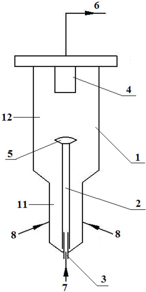
[0053] use figure 1 The shown equipment carries out metal pollution and hydrothermal aging on the catalytic cracking catalyst. Specifically, the catalytic cracking catalyst to be treated is fed into the aging device 1 from the top, and the fluidizing air is injected from both sides of the settling area 11 at the lower part of the aging device 1. After the temperature of device 1 was raised to 500°C, the fluidizing air was replaced with a fluidizing medium containing 50% by volume of water vapor, wherein, the superficial linear velocity of aging device 1 was 0.05m / s, and the average temperature was 750°C; the air was passed through The pipeline 3 leads into the riser 2, and the hydrocarbon oil containing metal-organic compounds is also passed into the riser 2 through the pipeline 3, and the hydrocarbon oil is bur...

Embodiment 2

[0055] This example is used to illustrate the metal contamination and hydrothermal aging method of the catalytic cracking catalyst provided by the present invention.

[0056] use figure 1 The shown equipment carries out metal pollution and hydrothermal aging on the catalytic cracking catalyst. Specifically, the catalytic cracking catalyst to be treated is fed into the aging device 1 from the top, and the fluidizing air is injected from both sides of the settling area 11 at the lower part of the aging device 1. After the temperature of device 1 is raised to 500°C, replace the fluidizing air with a fluidizing medium containing 50% by volume of water vapor, wherein the superficial linear velocity of aging device 1 is 3m / s, and the average temperature is 550°C; the air passes through the pipeline 3 into the riser 2, and the hydrocarbon oil containing metal-organic compounds is also passed into the riser 2 through the pipeline 3, and the hydrocarbon oil is burned in the riser 2, wh...

Embodiment 3

[0058] This example is used to illustrate the metal contamination and hydrothermal aging method of the catalytic cracking catalyst provided by the present invention.

[0059] use figure 1 The shown equipment carries out metal pollution and hydrothermal aging on the catalytic cracking catalyst. Specifically, the catalytic cracking catalyst to be treated is fed into the aging device 1 from the top, and the fluidizing air is injected from both sides of the settling area 11 at the lower part of the aging device 1. After the temperature of device 1 is raised to 500°C, replace the fluidizing air with a fluidizing medium containing 50% by volume of water vapor, wherein the superficial linear velocity of aging device 1 is 1m / s, and the average temperature is 650°C; the air passes through the pipeline 3 into the riser 2, and the hydrocarbon oil containing metal-organic compounds is also passed into the riser 2 through the pipeline 3, and the hydrocarbon oil is burned in the riser 2, wh...


PUM

PropertyMeasurementUnit
Densityaaaaaaaaaa

Abstract

The invention relates to a metal contaminating and water thermal aging method for a catalytic cracking catalyst. The method comprises the steps that firstly, under the lifting action of oxygen-containing gas, the catalytic cracking catalyst is conveyed in a lifting pipe from bottom to top; secondly, hydrocarbon oil containing a metal organic compound is sprayed into the lifting pipe for combustion, and the catalytic cracking catalyst is subjected to heavy metal contaminating; thirdly, the catalytic cracking catalyst obtained after heavy metal contaminating enters an aging device from the top of the lifting pipe; fourthly, with a fluidizing agent, the catalytic cracking catalyst obtained after heavy metal contaminating is subjected to water thermal aging in the aging device. The method is efficient, stable and capable of well simulating the nature of an industrial poiser.

Description

technical field [0001] The invention relates to a treatment method for catalytic cracking catalysts in the field of petroleum processing, in particular to a metal pollution and hydrothermal aging method for catalytic cracking catalysts. Background technique [0002] Catalytic cracking is an important secondary processing process and an effective means of lightening heavy oil. The main raw material is low-quality heavy oil, while the products are high value-added liquefied gas, gasoline, diesel, etc. Catalysts play an important role in product yield, smooth operation of equipment, and environmental protection. Due to the high activity of the fresh catalyst, direct use will cause negative effects such as an increase in coke production in catalytic cracking products and a decrease in gasoline octane number. Therefore, laboratory research work, whether it is process development, catalyst development and evaluation, or industrial raw materials Performance investigation, etc., a...

Claims


Application Information

Patent Timeline
IPC IPC(8): B01J37/10G01N1/28
Inventor 刘银亮张策金钰朱根权陈昀
Owner CHINA PETROLEUM & CHEM CORP
Why Eureka
Try Eureka