Eureka AIR delivers breakthrough ideas for toughest innovation challenges, trusted by R&D personnel around the world.

3D printing manufacturing method and equipment for porous three-dimensional part

A technology of 3D printing and production method, applied in the direction of additive processing, etc., can solve problems such as inability to achieve

Inactive Publication Date: 2016-05-11
GUANGDONG JANUS SMART GRP CO LTD
View PDF4 Cites 16 Cited by
  • Summary
  • Abstract
  • Description
  • Claims
  • Application Information

AI Technical Summary

Problems solved by technology

However, this technology can only be used to form solid three-dimensional resin parts, and it cannot be realized for some special requirements such as porous parts

Method used


Image

  • 3D printing manufacturing method and equipment for porous three-dimensional part

Examples


Embodiment 1

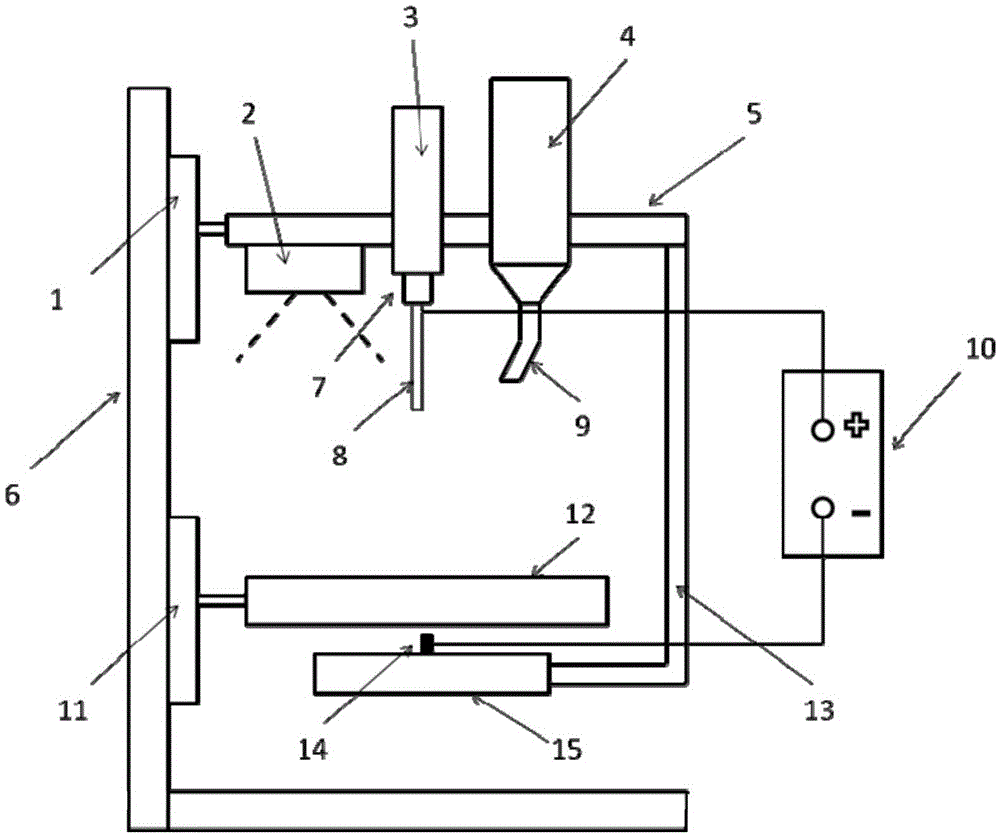
[0047] Firstly, a slurry for molding is prepared. The formula is as follows: 90% by mass of UV epoxy acrylate, and 10% by mass of polyethylene oxide aqueous solution. The above ingredients are mixed and stirred evenly to make a slurry for molding. A stainless steel needle with an inner diameter of 0.06 mm was selected as the nozzle, and connected to a high-voltage direct current power supply 10 device. The metal needle nozzle is connected with the positive pole of a high voltage direct current power supply 10 . An insulating receiving substrate 12 is arranged below the spray head, and a layer of polyvinyl alcohol (molecular weight: 98,000) powder is pre-laid on the receiving substrate 12, with a layer thickness of 50 microns. There is a needle-like or columnar electrode 14 below and is connected to the negative pole of the high-voltage DC power supply 10 . The slurry is stored in a container 3 and connected to the spray head through a conduit. Slicing and layering the thre...

Embodiment 2

[0049] Slurry composition for molding: 88% by mass of UV polyurethane acrylate, and 12% by mass of polyvinylpyrrolidone aqueous solution. A layer of polyacrylic acid (molecular weight: 100,000) powder is pre-laid on the receiving substrate 12 with a layer thickness of 40 microns. The voltage of the high-voltage DC power supply 10 is set at 25KV, an electric field is formed between the nozzle and the needle electrode 14, and the distance from the tip of the needle to the receiving substrate 12 is 12 cm. The molding process is the same as in Example 1. After the 3D printing is completed, the printed parts are cleaned several times with pure water and water vapor to dissolve the polyacrylic acid powder in the three-dimensional parts to form pores, thereby obtaining porous three-dimensional parts. Among them, the pore size is between 120 microns and 1000 microns.


PUM

PropertyMeasurementUnit
Pore sizeaaaaaaaaaa

Abstract

The invention discloses a 3D printing manufacturing method and equipment for a porous three-dimensional part. The method comprises the steps that a forming sizing agent comprising liquid photosensitive resin and a polymeric liquid additive is prepared, the liquid photosensitive resin can be cured through ultraviolet irradiation, and the polymeric liquid additive comprises a binder component and is provided with an electric conductor; the surface of a receiving substrate is coated with a layer of soluble polymeric powder; the sizing agent is sprayed to the receiving substrate according to a set program in an electrostatic spraying mode to form a layer of patterns; the sizing agent patterns on the receiving substrate is subjected to ultraviolet irradiation for curing; the cured sizing agent patterns are coated with another layer of the soluble polymeric powder, then sizing agent spraying and curing are conducted again, and the sizing agent and the soluble polymeric powder are overlaid layer by layer in this way to obtain a formed three-dimensional part; the formed three-dimensional part is cleaned through solvent and / or steam of the solvent, the soluble polymeric powder in the three-dimensional part is dissolved, pores are formed, and accordingly the porous three-dimensional part with the evenly distributed pores is obtained.

Description

technical field [0001] The invention relates to a 3D printing manufacturing method and equipment for a porous three-dimensional component. Background technique [0002] 3D printing is the technique of obtaining three-dimensional parts by adding material layer by layer. Among many 3D printing molding processes, light-curing 3D printing is a widely valued technology. The common light-curing 3D printing is to irradiate the light beam on the surface of liquid photosensitive resin according to a certain scanning path, so that a layer of resin in a specific area of ​​the surface is cured, and then cover a new layer of liquid resin, and then irradiate and cure. Layer-by-layer irradiation is superimposed to obtain a three-dimensional workpiece. This technology is often used in the production of models, prototypes, and handicrafts that require high precision. However, this technology can only be used to form solid three-dimensional resin parts, and it cannot be realized for some s...

Claims


Application Information

Patent Timeline
IPC IPC(8): B29C67/00B33Y30/00
Inventor 闫国栋王长明庞前列吕凝磊叶春生赵火平
Owner GUANGDONG JANUS SMART GRP CO LTD
Why Eureka
Eureka Blog
Learn More